Continue to Site

Welcome to EDAboard.com

Welcome to our site! EDAboard.com is an international Electronics Discussion Forum focused on EDA software, circuits, schematics, books, theory, papers, asic, pld, 8051, DSP, Network, RF, Analog Design, PCB, Service Manuals... and a whole lot more! To participate you need to register. Registration is free. Click here to register now.

please help me, these complex, complicated circuits

Status
Not open for further replies.

PG1995

Full Member level 5
Joined
Apr 18, 2011
Messages
248
Helped
1
Reputation
2
Reaction score
1
Trophy points
1,298
Activity points
3,758
Hi

If you find that this query doesn't belong here, then please move it to the section you deem appropriate. Thank you.

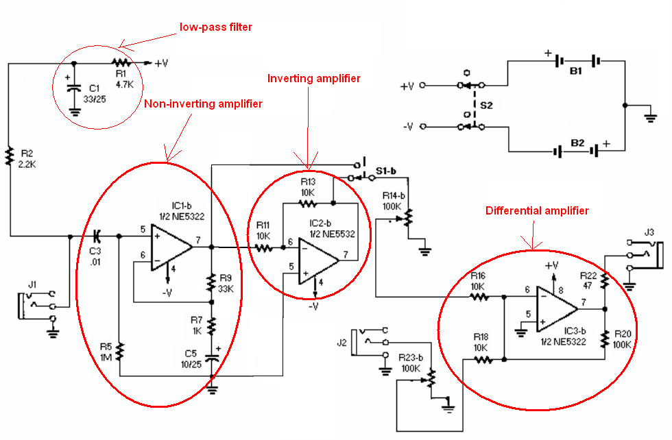
I don't know every time I open an electronics book I get very much afraid after looking at those circuits. As an example have a look here:
**broken link removed**

How do you keep track of such complicated and complex circuits when solving them at school? What is your advice for me to overcome this fear? Sometimes, I simply slip into depression after looking at those circuits in the book. Please advise me what to do. When you were at school how you kept the track and solved the circuit. With simple circuits like this one:
http://gangles.ca/images/SimpleCircuit.jpg

It is fairly easy to imagine what's going on in the wires and how electrons etc. are moving. In other words one can create a mental picture for such a simple circuit. But what about those fearful circuits? Please help me.
 

In each case you need to break things down in to bite sized chunks. In your second circuit you have a load resistor and two other resistors (25Ω). So, you combine those so you now have only one resistor to consider in place of three. Then you combine that with the next resistor (40Ω). Then you have just three resistors - two at 20Ω plus the new one you have calculated. You can even combine the two 20Ω ones. Don't try to look at it all at once.

The same applies to the larger circuit. Instead of trying to look at six opamps, follow the signal flow of one of the inputs from the jack J1. When you reach the switch, pick one position and ignore the other. When you have followed the signal through to find out what it does you can then consider the other switch position. Then you can look at the other signal path. It may not be quite obvious the way it is drawn, but the top half and bottom half are identical. If it was drawn better then that would be easier to see. Maybe draw yourself a block diagram to simplify it as you work out what each bit does.

So, analyse each bit at a time. Simplify things. Draw your own diagram. Scribble notes on the diagrams as you go.

Keith.

I don't think I could have said it much better than Keith. This is the same approach I take when analyzing some large, complex circuit or system. One of my favorite says is this: "How do you eat an elephant?....... One bite at a time." So, like Keith mentioned, find an input to the circuit and start tracing it's path. When you reach a point where another signal ties in, work back to find it's source, then walk through the second signal's path. Start at one end and work across the circuit.

Most complex circuits can be broken down into functional blocks. There may be logic gates, op-amps set in any variety of modes (but more are recognizable... inverting amplifier, integrator, comparator, etc), transistors (generally used as linear signal amplifiers or as a simple on/off current switch), etc. So, find a circuit element (and it's nearby parts) that looks familiar, and try to fit the circuit to something you've seen before. Once you have an idea what that block does, look at the circuit that it drives, and figure out what it does, and so on.

Heck, if the big circuit freaks you out, cover half of it up with a sheet of paper and pick through the uncovered side!
 

Hi PG1995,

of course, the recommendations from Keith + Enjunear show you the right way - no doubt about this.
On the other hand, I'll try to encourage you a bit.
May I ask you if the first circuit diagram you have posted originates from a standard textbook? I don't think so.
I am sure, each good electronic textbook is restricted to circuits that can be understood with the help of some suitable explanations. More than that, according to my experience it is even easier to develop a good working circuit step by step (and which may look very sophisticated) rather than to explain an existing circuit diagram in detail that was developped by somebody else.
So don't be to disappointed if you cannot understand the function of a complicated circuit diagram that was produced by advanced engineers - not in 1 hour but perhaps over days and weeks. Don't forget, very often there are some components in the circuit that help to improve some functional parameters without being absolutely necessary. This may complicate the way to understand the principle function.
My recommendation: Start with basic functional blocks and try to understand the task and the dimensioning of each component!
Good luck.
 

Looking at this circuit, MY mind does the following:

1) look at the types of connectors. The connector symbol, and the fact that it has two hot and one ground lead on both input and output tell me: STEREO AUDIO APPLICATION

2) The part number on the op amps tells me it is probably an old schematic, so nothing complicated about its function: PROBABLY A PREAMP OR AN EQUALIZER

3) I then look at the two switches. One is power supply, the other is a ganged DPDT. The circuit is symmetrical, and two of the switch inputs come from inverting op amps, the other two from non inverting op amps. Conclusion: IN-PHASE/OUT-OF-PHASE SWITCH

4) There are no additional switches or potentiometers, so there would be no way to adjust the gain or the frequency response. Conclusion: IT IS NOT AN EQUALIZER

So you put it all together and conclude that it is a: FIXED GAIN STEREO PREAMP WITH 0/180 DEGREE PHASING SWITCH
 

Many, many thanks all of you, Keith, Enjunear, LvW, Biff. Your replies are helpful and encouraging.

As Enjunear and Biff both mentioned the term "functional blocks", what are these "functional blocks" anyway? Any link to such blocks.

Regards
PG
 

Your opamp circuit has two identical channels. So you can analysis only one channel. And you can brake the circuit into the functional blocks quite easily.


Your opamp circuit has two identical channels. So you can analysis only one channel. And you can brake the circuit into the functional blocks quite easily.

Jony has the right idea, regarding a functional block breakdown of the circuit.

From a high-level view, a function block is just what it sounds like.... a "black box" that takes some inputs, and generates some know outputs, based on the inputs. Think back to your grade school math class, when you first learned about math functions. A function f(x), takes a variable, x, manipulates it, and returns that value. Example:
If f(x) = 2x+3,
Evaluate the following.... f(x)^2 - 5*f(x), when x=3
How do you go about solving it? You plug 3 in for x, evaluate the FUNCTIONAL BLOCK of math that is f(x), then stick it's output into the top-level equation, and finish evaluating. Like so:
f(3)=2*3+3... so f(3)=9, then
9^2 - 5*9 = 81 - 45 = 36

The same can be done for any complex system, from hydraulics, to biological process, to chemical reaction, nuclear power plant cooling systems, and even electronic circuits. So, like Jony showed, find a part of the circuit that looks like a common, well-known circuit and make a perimeter around it. Some signals come it, that well-known circuit performs a known task (amplifier, filter, inverter, etc), and supplies some defined output to the next item in the system. Once you've seen some of the standard circuits a few times, they will become easier and easier to identify.

It takes time to deconstruct complex circuits, so take your time, and pick through them one bit at a time. Look for circuits that you know, and then grow out and follow the signal flow from there. It takes practice, but sooner than you realize, you'll be ripping into complex circuits without any fear or hesitation.

When all else fails, you can always fire up PSPICE (or your favorite circuit simulator), build up a small part of the circuit, run some signals into it, and see what comes out the other side.
 
  • Like
Reactions: PG1995

    PG1995

    Points: 2
    Helpful Answer Positive Rating
It takes time to be familiar with the circuit.
A complex circuit is make up of many many simple functional block of circuits.
I use to have the same problem, until one day, I started to notice a pattern in the circuits.
The same pattern will starts to emerge.

When I start to apply the design, I also learn other pattern.
I used to teach my junior that the circuits that I design looks like inked stamps.
Every time when I need certain function, I will apply that stamping pattern in my schematic.
It was then that I collected many patterns, I starts to see them in other schematic.
The schematic looks complicated at first. If I re-lay the schematic in a pattern that I am familiar with,
I starts to see the pattern again. From there understand how the circuit works.

It takes practice & practice. Start to do hands on. You will catch it one day.
 

Status
Not open for further replies.

Part and Inventory Search

Welcome to EDABoard.com

Sponsor

Back
Top