Continue to Site

Welcome to EDAboard.com

Welcome to our site! EDAboard.com is an international Electronics Discussion Forum focused on EDA software, circuits, schematics, books, theory, papers, asic, pld, 8051, DSP, Network, RF, Analog Design, PCB, Service Manuals... and a whole lot more! To participate you need to register. Registration is free. Click here to register now.

ultrasonic transmitter

Status
Not open for further replies.

azam.jan

Newbie level 1
Newbie level 1
Joined
Jun 11, 2011
Messages
1
Helped
0
Reputation
0
Reaction score
0
Trophy points
1,281
Activity points
1,294
hi i am going to do my fyp on ultrasonic radar, and now want to draw my ultrasonic transmitter circuit using lm741 op amp. plz someone give me some link
thnx.

dont use sms or short hand typing skills in this forum... type the complete words by spending few more seconds. this is the last warning and further posts and thread of yours will be deleted without informing you if continued
 
Last edited by a moderator:

Hi,
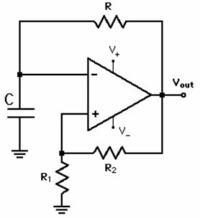
Configure 741 op amp in Astable Multivibrator mode. preferrably around 30khz. This would give you series of square pulses. Interface Ultrasonic Transducer at output.

Hope this helps...
 

A 741 won't be able to generate a 30 kHz square wave. It's more a triangle wave form. Do you know why?
 
May be because of slewrate
Yes, 741 is a bad ultrasonic driver for this reason. Most transducers need 40 kHz drive.
 
Last edited:

    V

    Points: 2
    Helpful Answer Positive Rating
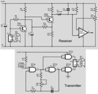
You can find a similar project here:
**broken link removed**

Also a possible option for an ultrasonic Transmitter is based on a 4011 quad 2-input NAND gate.


You can also use a 555-type circuit, transmission control will be enable using the pin 4 (RESET).
**broken link removed**
 
Referring to the 555 transmitter cicruit, I don't see a reasonable purpose for the transistor output stage. You can achieve the same result with less current consumption by connecting the transducer to the 555 output directly. For pulsed operation, an enable input to the 555 would be used in addition.
 

The output stage might be able to give a bit more 'kick' to the pulses but not wired the way it's shown. I would lose the two diodes and bypass the R5 with a capacitor. A capacitor across the supply would be advisable too. Check Vcb of the transistors will handle the voltage. Incidentally, some versions of 555 are only rated to produce as little as 2mA output current so a booster stage may be essential.

Brian.
 

Unless a special low power CMOS type is specified, I would assume a standard 555. It can easily drive a standard 40 kHz ultrasonic transducer. The only effect achieved with a pair of emitter followers is further reducing the output voltage.
 

Status
Not open for further replies.

Part and Inventory Search

Welcome to EDABoard.com

Sponsor

Back
Top