Continue to Site

Welcome to EDAboard.com

Welcome to our site! EDAboard.com is an international Electronics Discussion Forum focused on EDA software, circuits, schematics, books, theory, papers, asic, pld, 8051, DSP, Network, RF, Analog Design, PCB, Service Manuals... and a whole lot more! To participate you need to register. Registration is free. Click here to register now.

Wein Bridge Osc no go

Status
Not open for further replies.

davenn

Advanced Member level 3
Joined
Jul 1, 2009
Messages
841
Helped
192
Reputation
384
Reaction score
163
Trophy points
1,323
Location
Sydney, Australia
www.sydneystormcity.com
Activity points
6,382
Wien Bridge Osc no go

Ok, am about to give up and start doubting my 40+ yrs of electronics experience
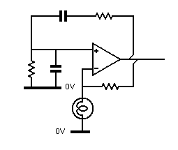
I cant make a simple Wien bridge Osc work

**broken link removed**

the cct looks ok when compared to various appln notes from places like Texas Inst. etc

for simplicity I have just used the pair of 100nF caps so as to leave out the complication of band switching etc

OK just for the record....
DC voltage readings around the LF351
PIN --- Voltage
1 ------- -9.28V
2 ------- 0V
3 ------- 0V
4 ------- -9.45V
5 ------- -9.25V
6 ------- -7.2V
7 ------- +9.46V
8 ------- 0V
 

Attachments

  • sinegen-small.gif
    sinegen-small.gif
    14.1 KB · Views: 241
Last edited:

Re: Wien Bridge Osc no go

hi FvM,
will have a look at that tomorro :) the osc isnt with me at the moment

thanks for your thoughts, will let you know what I find

Dave
 
Last edited:

Re: Wien Bridge Osc no go

thanks FvM,

You were spot on, manufacturing error ... I had forgotten the wire link from the output (pin 6) to the wiper/top side of the 1k pot.
so hence a hole in the feedback path. Doh!!
OK next issue.... the osc works.. BUT its a perfect sqr wave rather than a sinewave as its supposed to be.
now once again to simplify operation I had removed the dual ganged freq adj pot and replaced with 10k resistor (metal film, within 0.2k of each other) So they along with the 1k resistors gives 11k in each of those networks ( the RC series and the RC parallel) (100nF caps).

Adjusting the 1k feedback trimpot also adjusts the freq, so I have discovered. Tho the project paperwork says that the 1k pot is supposed to adj the distortion level. Adjusting that pot varies the output freq from 28Hz to ~ 55Hz. the output is still a good sqr wave regardless of the pot setting.

Any further thoughts ?

thanks
Dave
 
Last edited:

There are two possible ways to get a square-wave output:
- negative feedback too low (1k pot resistance should be decreased)
- OP output overload
Unfortunately increasing the negative feedback also increases the output load

Changing the oscillator frequency when the gain is far away from regular wien bridge design isn't surprizing.

P.S.: I found National AN-31, the Wien bridge oscillator uses a 10V/14 mA lamp with a fixed 750 ohm resistor in the negative feedback path. The dimensioning seems to better fit the limited OP output current range.
 
Last edited:
  • Like
Reactions: davenn

    davenn

    Points: 2
    Helpful Answer Positive Rating
Re: Wien Bridge Osc no go

There are two possible ways to get a square-wave output:
- negative feedback too low (1k pot resistance should be decreased)
- OP output overload
Unfortunately increasing the negative feedback also increases the output load

Changing the oscillator frequency when the gain is far away from regular wien bridge design isn't surprizing.

P.S.: I found National AN-31, the Wien bridge oscillator uses a 10V/14 mA lamp with a fixed 750 ohm resistor in the negative feedback path. The dimensioning seems to better fit the limited OP output current range.

ok ohh btw the lamp Im using in mine is a 12V 50mA, should be ok accourding to the original design notes in the first post

will try a fixed value feedback resistor ( thanks for that national AN31 saved a copy)

wondering if I should try another type of op amp will have a look around see what I have maybe an old 741 or something.
I dont want hi freq, actually aiming for something ~ 10 - 20 Hz for testing the preamps for my seismograph system.

cheers
Dave

PS .. what really annoys me is that this well laid out article surely must have worked for that guy ?? Its not like many circuits posted on the net with next to no explanations about their operation.

---------- Post added 29-04-11 at 00:20 ---------- Previous post was 28-04-11 at 23:58 ----------

please just refresh my old memory ;)

f = 1/ 2pi RC R in ohms obviously, C in Farads ? pretty sure

so 1/ 6.282 x 11000Ω x .001F

= 1/ 36.102 = 0.0277 (Hz ?)

doesnt look right my maths really sux :oops:

Dave
 

Re: Wien Bridge Osc no go

The amplitude controlling components should have no effect on the frequency.
2 x 100k and 2 x 0.1µF will give a frequency of 15.9Hz

The amplitude controlling 10k pot on the output doesnt have an effect on freq. its the 1k feedback pot that does.

can you correct my formula maths in my previous post please or at least show the working for your values and resulting freq so I can follow it :) ?

Im getting 28Hz with my values (11k and 0.1u) its just a sqr wave rather than a sine wave

thanks
Dave
 

The 1k variable and the lamp (should) control the amplitude of oscillation.
If the output amplitude increases, the current through the lamp increases and its resistance goes up. That increases the negative feedback to compensate.

If that's not happening there's something amiss in that part of the circuit - and there ain't much of it to investigate. You haven't got the lamp and 1k pot changed over have you?


The formula you quote for frequency in the earlier post is correct: f = 1/ 2pi RC

I started with a required frequency of 15Hz and a capacitor of 0.1µF. The formula becomes R = 1/ 2pi fC

R = 1/ 6.28 x 15 x 0.1^-6 = 106,157Ω

So, using 100k instead, f = 1/ 2pi x 100,000 x 0.1^-6 = 15.9


There are more elaborate methods of amplitude control which are faster in operation, such as the one I used here 3-phase sine-wave generator
After publication, a correspondent suggested a modification to it which used a single potentiometer instead of a dual.
 
Last edited:

Re: Wien Bridge Osc now going, but sqr instead of sine

The 1k variable and the lamp (should) control the amplitude of oscillation.
If the output amplitude increases, the current through the lamp increases and its resistance goes up. That increases the negative feedback to compensate.
If that's not happening there's something amiss in that part of the circuit - and there ain't much of it to investigate. You haven't got the lamp and 1k pot changed over have you?

yes sorry we were travelling different lines of thought. yes thats the purpose of the lamp, positive temp co-efficient to stop an amplitude runaway situation.

the freq is stable as is the amplitude as can be seen from the scope screenshot.... its just sqr instead of sine!! :(

attachment.php


Thats with .47u and 10kΩ and a 330Ω feedback

The formula you quote for frequency in the earlier post is correct: f = 1/ 2pi RC
I started with a required frequency of 15Hz and a capacitor of 0.1µF. The formula becomes R = 1/ 2pi fC
R = 1/ 6.28 x 15 x 0.1^-6 = 106,157Ω
So, using 100k instead, f = 1/ 2pi x 100,000 x 0.1^-6 = 15.9

Thanks for that ... I didnt have enough 0's when converting .1u to Farads

There are more elaborate methods of amplitude control which are faster in operation, such as the one I used here 3-phase sine-wave generator
After publication, a correspondent suggested a modification to it which used a single potentiometer instead of a dual.

ok will have a nosey at that

cheers
Dave
 

Attachments

  • DSCF5197a.jpg
    DSCF5197a.jpg
    66.1 KB · Views: 367

I've tried this circuit, it worked with an ra53 thermistor which I think was designed for the pupose, but getting a distortion free sine was tricky with a bulb, the best results I got were with a 1.5v bulb.
I suspect the bulb is giving you trouble as well.
 
  • Like
Reactions: davenn

    davenn

    Points: 2
    Helpful Answer Positive Rating
Re: Wien Bridge Osc no go

hey Doc :)

oh interesting, I used to have some glass encapsulated thermistors around maybe have some other small disc ones too
dang my glass ones must still be back in New Zealand, will have to try the disc ones.... dunno if they are NTC or PTC. Will see if I can find the glass ones in storage at mom and dad's when I visit next week :)

I presume the RA53 ones you were referring to were like in this datasheet..... ?
**broken link removed**

cheers
Dave
 

I don't understand the discussion about frequency formulas. It should be clear, that the wien bridge frequency formula only applies to sine waveforms, in other word it has two prerequisites:
- almost linear amplifier operation
- steady state operation with correct feedback factor

Unfortunately, I can't see from the output waveform only, why your circuit isn't working correctly.
If the about +/- 5V square wave is showing the OP output, it's preferably a case of output overload.

Regarding lamp selection, please notice these words from the original publication:
The bulb used here is a 6V 60mA type Maplin code BT99H. A 12 Volt bulb rated 60mA or 40mA will also work.
Are you sure, that the author ever tried? You also have to expect different behavior of lamps with same nominal specification.

You can check the principle circuit operation by placing a variable resistive divider instead. With a feedback factor slightly below -1/3, you should get it working, although clipping at the supply rails is the only amplitude control mechanism in this case.

As a rule of thumb, the cold resistance of a tungsten filament ist about 1/10 of the value in nominal operation. If the OP and feedback resistor doesn't source sufficient current to heat up the filament, amplitude control operation will never start.
 
  • Like
Reactions: davenn

    davenn

    Points: 2
    Helpful Answer Positive Rating
Yes its exactly like those, my circuit is long gone, at least I think, it was a circuit for testing distortion in audio power amplifiers that I was working with at the time.
You can still get them, but they are more of a specialist supplier thing these days, fets seem to have taken over like in the interesting schematic further up.
 

Re: Wien Bridge Osc no go

Hi Doc and FvM

monday morn and back in the workshop. some more dabbling over the last 1-2 hrs and have had success.
I tried several of the different thermistors I brough from home... no idea of if they were/are NTC or PTC. tried one in the cct and initially still the sqr wave. did some really fine adj of the 5k feedback trimpot and found a spot where I actually got a sine wave. BUT oh oh so critical to find that spot. So went to a 1k pot and that was a little easier. ended up with a miniature 10turn 100Ω trimpot. and could find the sweet spot. I noticed tho that after a short time the "stable" (not quite) oscillation would drop in amplitude and die. Warming the thermistor restored the osc. Tried several of the thermistors with similar results.

Went back to the 12V, 50mA globe and was able to get a sinewave again.
It is interesting to watch the signal on the scope go though 6 or so cycles of varying and decreasing amplitude before settling down to a stable signal, both in freq and amplitude.
It didnt do that with the thermistors, just the globe.

55861d1304292318-dscf5199a-small.jpg


Thanks so much for your input, its been an interesting learning experience.

I dont normally play at this end of the freq spectrum. Most of my work is up in the UHF - microwave bands.
Just have to see if I can now get it down to ~ 10 - 15Hz and still be stable.
Will still see if I can find those glass bead thermistors back in New Zealand when I visit next week.

cheers
Dave
 

Attachments

  • DSCF5199a-small.jpg
    DSCF5199a-small.jpg
    82.4 KB · Views: 223

Re: Wien Bridge Osc no go

Well done with your result, there are 2 solutions to give a more stable o/p and a quicker to settle ckt, 1) to use a JFET to modulate the gain of such an oscillator, & 2) use some "soft" back to back zeners (or zeners with low value resistors) to limit the amplitude and stabilize the ckt (in place of the bulb), the Jfet ckt is a bit more complex and linked to the desired o/p level pot, regards Orson Cart.

**broken link removed**

top left page 8.
 

Re: Wien Bridge Osc no go

Hi Orson,

thanks :) it was one of those eureka moments :) final success.

Yes the FET idea ... already in the works have breadboarded this one up it will be getting power on tomorro :) will be interesting to see how it goes.....

attachment.php


cheers
Dave

PS hey where in NZ are you ? Will be in CHCH next week to see my kids. my home area is Dunedin. Been in Australia for last 11 yrs
 

Attachments

  • ckt18_1.gif
    ckt18_1.gif
    4.2 KB · Views: 346

Re: Wien Bridge Osc now working, experiminting with variations

hi guys,

decided to keep this thread alive whilst I continue to play with different variations of the Wien Bridge Osc. It may be of use to others that also want to experiment.

As mentioned in my last post I was breadboarding a variation with 2 opamps and a FET. 2 variations to the values stated in the cct....
1) ... + - 9V instead of 12V
2) ... a 2N5485 FET instead of the 2SK30A (couldnt find one)

here is the resulting waveform.....

attachment.php


note the fuzzyness to the right end of the waveform, as the signal increases in amplitude it also increases in instability. The waveform is pulsing up and down in amplitude.
Am going to try several different FET's and see if that has any bearing on the results

cheers
Dave

I just tried compressing the X axis of the scope going from the 500uS in the above image, to 2mS interestingly the amplitude doesnt continue to increase but rather reaches a peak and then smoothly dies off again.
This is all new to me ... I have no idea of how to explain what is actually occurring...
anyone care to take a stab at it ? :)
 

Attachments

  • DSCF5204a-small.jpg
    DSCF5204a-small.jpg
    53.8 KB · Views: 328
Last edited:

IC 2/2 is controlling the gain by precision rectifying the output to produce a voltage to control the resistance of the fet.
From you waveform, the gain of 1/2 is not over unity enough.
Because the fet is operating in the linear region, its selection may be highly critical for correct operation.
I would increase R4 to give it more gain as a try.
 

I would increase R4 to give it more gain as a try.
Or decrease it a bit....

The actual problem is too much gain and/or delay in the amplitude control loop. Unfortunately, this parameters are designed ino the controller circuit and can't be easily modified. Also the JFET parameters as well as the ratio of R3/R4 affects it. Due to the nonlinear FET characteristics, I have difficulties to predict the behaviour. I would check it in a simulation or tune the parameters empirically.
 

Status
Not open for further replies.

Part and Inventory Search

Welcome to EDABoard.com

Sponsor

Back
Top