Continue to Site

Welcome to EDAboard.com

Welcome to our site! EDAboard.com is an international Electronics Discussion Forum focused on EDA software, circuits, schematics, books, theory, papers, asic, pld, 8051, DSP, Network, RF, Analog Design, PCB, Service Manuals... and a whole lot more! To participate you need to register. Registration is free. Click here to register now.

12 volt 10A powersupply

Status
Not open for further replies.

nxt_

Member level 4
Member level 4
Joined
Aug 16, 2010
Messages
69
Helped
4
Reputation
8
Reaction score
4
Trophy points
1,288
Location
Egypt
Activity points
1,834
hey everyone,
Kindly could anyone check this schematic for 12volt 10A powersupply. here is the question! i want to know what exactly the tip2955 transistors do to support the 10A. as far as i know the 7812 regulator its capacity is 1A even the T-type its maximum capacity is 3A so how the three transistor act to support this current. i'll be gratefull to know how it works and what is the equations i need to know. if i want to rais the current.

here is the url:\

h**p://2.bp.blogspot.com/_7LQX0wDXg-o/S6pKBvSrN9I/AAAAAAAAAys/hgyUrY7YjEw/s1600/12v-15a-voltage-regulator-_circuit.jpg


Many Thanks For Your Attention.
Regards.
Ahmed
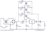
 

Attachments

  • 12v-15a-voltage-regulator-_circuit.jpg
    12v-15a-voltage-regulator-_circuit.jpg
    51.7 KB · Views: 240

Looks fine. I will use 2n2955's with lots of heatsink
 
  • Like
Reactions: nxt_

    nxt_

    Points: 2
    Helpful Answer Positive Rating
To understand it you have to realize what R1 does.

At low currents the 7812 works just like any other linear regulator, the transistors do nothing because there is less than the 0.65V between their base and emitter pins needed to make them conduct.
As the current increases, so does the voltage dropped across R1. At around 650mA the voltage dropped is sufficient to make the transistors conduct and pass current directly between the input and output. The voltage is still stabilized by the 7812, if it is pulled down, the voltage across R1 gets larger and the transistors conduct more, if the voltage tries to go above 12V, the 7812 stops conducting, no current flows through R1 and the transistors turn off. In normal use the circuit reaches a state of equilibrium where the 7812 passes at most 650mA and the remaining current is shared between the transistors.

R2, R3 and R4 are there to help balance the current through the transistors, without them if one transistor had a slightly lower Vbe than the others it would hog all the base current.

Within reason you can add more parallel transistors to increase the current capacity but you will reach a point where it can no longer provide enough base current and all you get is partially conducting transistors. You can use Darlington transistors but you would have to change the value of R1 to take into acount their higher Vbe requirement.

Brian.
 
'omielectronics' how can you say that without knowing the input voltage, ambient temperature and whether it has a heat sink.
The current through it is limited to about 650mA so it should be well within it's design ratings.

Brian.
 
  • Like
Reactions: nxt_

    nxt_

    Points: 2
    Helpful Answer Positive Rating
omielectronics : did you try it? and find that the 7812 is hot?
betwixt: "The voltage is still stabilized by the 7812, if it is pulled down" ---> what do you mean by "Pulled Down" ?. and if my calculations is right then the transistors will not conduct unless the LOAD CURRENT IS ABOUT 1.1A ~ 1.2A,. (thats why omielectronics saying that the transistors is hot i guess he used 7812 rated 1A., i think this circuit will be just fine if we try 7812 with 3A capacity. . " also i guess the resistors need to be well calculated.

Many Thanks For your Attention

---------- Post added at 22:05 ---------- Previous post was at 21:34 ----------

one more thing.. the idea of putting parallel transistor is it effiecient for this circuit.. i mean do i want to consider the HFE (dc current gain).. i guess the current gain is diffenert even if the transistors are the same.. is it aproblem in this circuit. and if it is aproblem what i want to do to build aperfect 12v 10A power supply. also.i used tip2955 before for motor driving and i remmember that i had to put pull down resistor on the base. otherwise the motor was still running even when i removed the base signal. do i need to put this pull down resistors in this circuit?

Again many thanks for your attention.
 

The transistor start to conduct when the voltage betwen their base and emitter pins reaches about 0.65V. The voltage is created by the drop across R1 which should have a value of 1 Ohm, not 0.1 Ohms as shown. So when the current through R1 reaches about 650mA, the transistors start to conduct and the remaining load current flows through them. If the load on the 7812 drops below 650mA the transistors shut off and only the 7812 carries the current.

Its a fairly standard circuit and has the advantage that it uses the regulator to do the voltage stabilizing, has thermal shutdown protection, and only uses the transistors to handle heavy loads.

If you want to expand the number of transistors so increase the load capacity, consider using darlington types because they have lower base current requirements. All you have to remember is that because they have two PN junctions betwen their base and emitter pins, they need twice the turn-on voltage so R1 needs to be twice the value.

You don't need pull-down resistors, R1 and the emitter resistors already make sure they turn off when the load current reduces.

Brian.
 
  • Like
Reactions: nxt_

    nxt_

    Points: 2
    Helpful Answer Positive Rating
thanks betwixt, i have another question. i want to put aferrite core after the bridge directly.. actually i want to put 2 cores, one on the +ve side and one on the negative side. how is that sounds.. i want to stablize the current and reduce the noise . cuz this supply will be attatched to microcontroller circuit.
 

You can do that if you feel it is necessary. It will do nothing to stabilize the current but it might help to filter out power line noise. I would suggest you fit a capacitor or about 1nF across each of the bridge diodes as these may introduce noise of their own and also fit a common mode choke in the lines between the bridge and the reservoir capacitors. You might get better results with a single core and two windings on it, one for + and one for - lines rather than put a core in each individually.

Brian.
 
  • Like
Reactions: nxt_

    nxt_

    Points: 2
    Helpful Answer Positive Rating
anyway, you could try to use 7812 , look what effect it is . i think it is too hot for my products, because my product' pcb boards are very small.
 

The heat generated by the 7812 has nothing at all to do with the size of board. Use Ohms Law to work out how much power it has to dissipate, (Voltage across it * Current through it) Watts.
From the data sheet you can work out the temperature rise per Watt and then calculate the size of heat sink needed to keep the temperature within safe limits.
In any case they are not capable of carrying 10A alone.

Brian.
 
  • Like
Reactions: nxt_

    nxt_

    Points: 2
    Helpful Answer Positive Rating
anyway, you could try to use 7812 , look what effect it is . i think it is too hot for my products, because my product' pcb boards are very small.

Hi,
You have to consider the specific circuit you're using. Say you have an input voltage of 15v and are driving load (from the 7812) that draws 0.5A. The current flowing through the circuit is 0.5A. The voltage dropped across the 7812 is (15v-12v), ie 3v. So, the power dissipated across the 7812 is 3v*0.5a = 1.5va = 1.5W.

BUT, if your input voltage is 25v (within the limit of 7812), and your load is still 0.5A, the power dissipated across the 7812 is VI = (25-12)*0.5 = 6.5W. HUGE.

If you don't have a heatsink, both will get hot. But the 7812 in the second scenario will get WAY hotter and possibly be damaged as it is beyond the acceptable range of the 7812 power dissipation (with no heatsink) which is around 2.5W (check datasheet).

So, 7812 will get hot, how hot depends on input voltage and output load, but you SHOULD use a heatsink, unless power dissipated across the 7812 is very small. If the heat and/or heatsink is a problem, consider using a switching regulator. You are likely to be pleased with the results. They are much more efficient. Consider taking a look at L497x, L496x series regulators from ST. There are many more.


Now, considering the above circuit, where the 7812 passes max approximately 650mA, if input voltage is 15v, power dissipated across 7812 is 1.95W. If input voltage is 25v, power dissipated across 7812 is 8.45W (!!!!!! BEWARE !!!!!). These are of course maximum power calculations, so, make sure you use a good heatsink.

Hope this helps.
Tahmid.
 
Last edited:
  • Like
Reactions: nxt_

    nxt_

    Points: 2
    Helpful Answer Positive Rating
Status
Not open for further replies.

Similar threads

Part and Inventory Search

Welcome to EDABoard.com

Sponsor

Back
Top