Continue to Site

Welcome to EDAboard.com

Welcome to our site! EDAboard.com is an international Electronics Discussion Forum focused on EDA software, circuits, schematics, books, theory, papers, asic, pld, 8051, DSP, Network, RF, Analog Design, PCB, Service Manuals... and a whole lot more! To participate you need to register. Registration is free. Click here to register now.

Need A Help(Light Dimmer and Fan Regulator)

Status
Not open for further replies.

amsbhole07

Member level 1
Member level 1
Joined
Oct 28, 2010
Messages
35
Helped
0
Reputation
0
Reaction score
0
Trophy points
1,286
Activity points
1,535
Hi ,


I want to make the light dimmer and Fan regulator in one project.

Can anyone help with the schematic.

As i have little bit idea i am using MAC15 Triac,
MOC3021 Optocoupler,But it dont know how it will work.

How zero crossing will work.

How to select the resistor and capacitor value.


Please reply soon
 

using micro controller or general electronics i am not clear because this section is microcontroller section would you clarify
 

Hi,
For starters, read through this:
Phase fired controllers - Wikipedia, the free encyclopedia
**broken link removed**

The zero crossing detectors presented here are simple and safe. There are simpler ways to do it, eg, using optocoupler, but it looks like you're a begineer and non-isolated circuits are very risky.

Research on zero crossing detectors and phase angle control through google. There are many articles and sample codes provided. Once you get a grip of things, then get into the coding part, but be clear on these as you are dealing with mains here.

Hope this helps.
Tahmid.
 

Hi,
please refer the attached jpg image i have made the handdrawing of it.
i am using the Psoc Cypress Capsense IC As to deal with this IC it is Very sensitive .So Before using this i need to be sure of the circuitry.Just check the circuit and give me the feedback .This circuit will work on 230v Ac Supply.
Triac MAC15 is ok ?

What will the input of the NAND Gate and why it is required ?
Please reply
 

Attachments

  • 1.jpg
    1.jpg
    108.3 KB · Views: 271
  • 1.jpg
    1.jpg
    423.9 KB · Views: 268
Last edited:

I think you forget to connect one end of bridge rectifier to neutral line.

NOTE : THIS CIRCUIT USES DIRECT 230V. YOU SHOULD BE VERY CAREFUL WHILE CHECKING.
IF YOU ARE NOT EXPERIENCED, DONT TRY THIS ONE.
 

Ya i forget to connect the Neutral line.
Is there any other option .

---------- Post added at 12:05 ---------- Previous post was at 11:46 ----------

Which triac is suitable for light dimmer and Fan speed controller

---------- Post added at 13:04 ---------- Previous post was at 12:05 ----------

please tell how can i select the triac that is suitable for light dimmer and fan regulator application that works on 230v Ac supply.
 

Hi,
You need to calculate how much power you need the triac to drive. Eg. If you use a standard wall fan, let's it as 80W, and incandescent lamp of 100W, that's a total of 180W. Your MINIMUM line voltage, let's assume is 180V. So, that's a current = 180/180 = 1A. So for safety purposes, use a triac that can handle 2-3A. I'd go for BT136-4A. That's a common triac used in dimmers and not very expensive.

Hope this helps.
Tahmid.
 
thanks this information is useful to me.

But one query can i operate Fan and Light on one triac by giving parallel connection

---------- Post added at 14:21 ---------- Previous post was at 14:00 ----------

thanks this information is useful to me.

But one query can i operate Fan and Light on one triac by giving parallel connection


If it is possible can i use MOC 3041 Optocoupler (inbuilt zero crossing Detector) is there.

Please suggest
 

Hi,
If you mean connecting the fan and light parallel, then what's the problem. Have the light and fan connected in parallel. However, you will be varying both speed of the fan and brightness of light this way. If you want to control fan speed and light brightness individually, then you must have two units controlling their respective loads.

Hope this helps.
Tahmid.
 

hi,

thanks for the update.

please tell me about zero crossing how can i built up the zero crossing .
You have any schematic of it .


Please reply soon.
 

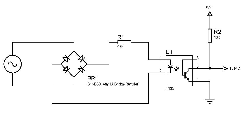
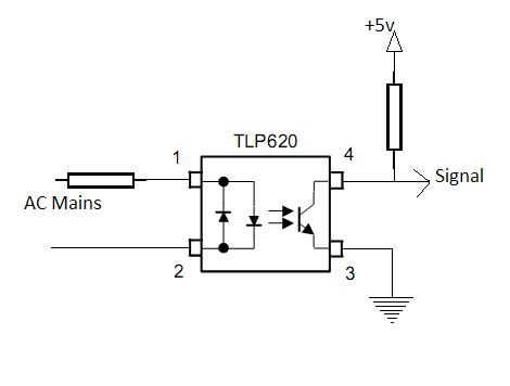
Take a look at these (These are what I use):
87_1289390177.jpg


19_1289390196.jpg


Hope this helps.
Tahmid.
 
Last edited:

hi,

In this circuit which part is the zero crossing ciruitry.


Please clarify and how it works.

Please help me
 

hi,

In this circuit which part is the zero crossing ciruitry.


Please clarify and how it works.

Please help me

Ordinary dimmer (like the circuit shown above) does not require zero crossing. Zero crossing is required only if you are using a microcontroller.

Clarify your requirement, whether you are using a micro or not.
 

Hi,

The whole thing is the zero-crossing detector. It works like this:
The AC voltage is changing value and direction and is converted to DC. Whenever the value gets lower than 1.4v, ie, it starts approaching the zero crossing point, the LED turns off, while, at all other times, the LED is on. Since the LED turns off, there is a +5v present at the signal pin. At all other times, the output is 0 as the LED is on and so the transistors pulls it to ground.
In the 2nd diagram, I used the TLP620 which is a special optocoupler containing 2 anti-parallel LEDs, thus requiring no bridge rectifier. Here also the operation is similar.

So around the zero crossing point, there is a +5v signal that the microcontroller must detect, maybe using an interrupt or even using polling.

Hope this helps.
Tahmid.
 

hi,

Just see the attached image i want to chech the zero crossing ciruitry before desining with Capsense IC.

I work with this circuitry using Microcontroller 89c52.

But it is not working please help me out

---------- Post added at 11:49 ---------- Previous post was at 11:46 ----------

hi

i need to check the zero crossing detector circuit.

But i dont have the oscilloscope


I tried to connect the LED at the output of collector of theTransistor and connected the zero crossing ciruit to microcontroller 89c52 .as per the attached circuitry


But the Led is not glowing .i have used BC547 transistor what will be the output of Transistor 5v /0v
But it is not working please help me out
 

How did you connected the led?

The Anode of the led should be connected to +ve through a current limiting resistor (typically 330E for 5V). The cathode should be connected to the collector of the transistor.

Even though the led will be blinking at the rate of 100Hz.
 

please explain how this circuit work what will be output at collector


Status
Not open for further replies.

Similar threads

Part and Inventory Search

Welcome to EDABoard.com

Sponsor

Back
Top