Continue to Site

Welcome to EDAboard.com

Welcome to our site! EDAboard.com is an international Electronics Discussion Forum focused on EDA software, circuits, schematics, books, theory, papers, asic, pld, 8051, DSP, Network, RF, Analog Design, PCB, Service Manuals... and a whole lot more! To participate you need to register. Registration is free. Click here to register now.

Weird loop gain and phase margin plot

Status
Not open for further replies.

sjamil02

Member level 4
Member level 4
Joined
Nov 8, 2009
Messages
72
Helped
9
Reputation
18
Reaction score
5
Trophy points
1,288
Location
United Kingdom
Activity points
1,961
Hi All,

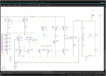
When I simulated the loop gain and phase margin (See attached schem for sim setup), the simulation results look's strange. How to measure phase margin from the plot? Is the simulation result correct? If not, how to get the correct result?

Note: The circuit is shunt regulator and I did not put compensation capacitor yet. For the loop gain setup, L=1mH and C=100uF.
 

Attachments

  • SimSetup.jpeg
    SimSetup.jpeg
    174.9 KB · Views: 219
  • LoopGain_PhaseMargin.jpeg
    LoopGain_PhaseMargin.jpeg
    272.1 KB · Views: 243

Hi All,

When I simulated the loop gain and phase margin (See attached schem for sim setup), the simulation results look's strange.
.............
.

Which part do you consider as "strange" - and why?
Your graph is hard to read - however, it looks like a 2nd order system and the gain seems to be below unity (neg. dB values).
Is this correct?
 

Hi lvW,

Hopefully the new attachment is more clearer. Yes, the graph is in negative -dB and that is why i said it looks strange. This is my first time designing shunt regulator and I was expecting the loop gain to be in positive dB and I don't have ideas how to measure phase margin from the graph. Is there something wrong with my circuit or my simulation setup?

Another question, is it correct to model the power supply input current in my schematic? I put a dc source (Vdd=1V) with a series resistor (100mOhm --> package+ball resistance).
The load current is modelled using a resistor of 100ohm. The output capacitance is on-die capacitor (decap) + on-die series resistor.

Please help.

Thks
sj
 

Attachments

  • SimSetup.jpeg
    SimSetup.jpeg
    148 KB · Views: 165
  • LoopGain_PhaseMargin.jpeg
    LoopGain_PhaseMargin.jpeg
    345.8 KB · Views: 192

Yes, the graph is in negative -dB and that is why i said it looks strange. This is my first time designing shunt regulator and I was expecting the loop gain to be in positive dB

Yes, the loop gain must be positive.

...and I don't have ideas how to measure phase margin from the graph. Is there something wrong with my circuit or my simulation setup?


The phase margin is determined at a frequency with loop gain=0 dB. This point cannot be identified in your graph.
However, I cannot comment to your simulation setup since it is still very hard to detect. Please try to create a block diagram.
And don't forget: Opening the loop for injection of a test signal destroys the operatiing point. There are specific procedures to circumvent such problems. Are you familiar with loop gain simulation alternatives?
 

Another question, is it correct to model the power supply input current in my schematic? I put a dc source (Vdd=1V) with a series resistor (100mOhm --> package+ball resistance).
In other words, the regulator operation depends on the ability of the output transistor to short a 100 mohm source. Can it? It's only W=6µ.

I don't see an AC source to set up a gain measurement. Where is it?

P.S.: is there really a 1m/100u LC low-pass in the loop? Driven by a 10k node? What it's good for?
 
Last edited:

Thanks LvW and FvM.

LvW,

I slightly modified my circuit as following:
The input current is set to 20mA--> Iin=(Vsupply-Vref)/Rseries=(1V-0.9V)/5ohm=20mA. Is this the correct method to design shunt regulator?
The maximum load current is set by the resistor (Rload=47ohm-->Iload_max=19mA). During heavy load, 19mA current flows through load resistor and 1mA through the shunt transistor. During 0A load, all the 20mA current is shunted through the transistor. Please correct me if i'm wrong.
Btw, the error amplifier is supplied with another supply voltage of 2.5V.

The phase margin is determined at a frequency with loop gain=0 dB. This point cannot be identified in your graph. However, I cannot comment to your simulation setup since it is still very hard to detect. Please try to create a block diagram
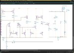
Please refer to the attached block sim setup.

Opening the loop for injection of a test signal destroys the operatiing point. There are specific procedures to circumvent such problems. Are you familiar with loop gain simulation alternatives?
I am not familiar with loop gain simulation alternatives. Can you please guide me on the steps to do this in cadence? Any reference materials or link will be helpful too.

FvM,

In other words, the regulator operation depends on the ability of the output transistor to short a 100 mohm source. Can it? It's only W=6µ.
The shunt transistor size is 6um/0.3um <56:1> = 336um/0.3um.

I don't see an AC source to set up a gain measurement. Where is it?
P.S.: is there really a 1m/100u LC low-pass in the loop? Driven by a 10k node? What it's good for?
I used 1mH inductor and 100uF capacitor and injected AC test signal for loop gain measurement. This is the only method that i am familiar with. Please suggest a better ways.

Thanks again
sj
 

Attachments

  • SimSetup.jpg.jpeg
    SimSetup.jpg.jpeg
    109.7 KB · Views: 187

I think, for high frequencies the RL concept with L=1mH and C=100uF can be sufficient (better: Use larger values for both) - in particular when you are interested in the phase margin only.
But where do you pick up the output signal caused by the ac input? It must be measured at the right side of the inductor.
 

I couldn't detect the roughly pixeled "acm=1" before. The auxilary circuit can work, as long as you are measuring Vreg instead of the voltage right of the inductor, which is partly shorted by the inductor load. An ideal buffer, or simply a sufficient high impedance RC low pass would be needed for an exact "measurement".

What's the loop gain with the modified dimensioning? If it's still too low, you should trace the AC magnitude through the amplifier stages for an unexpected attenuation. Visualizing the DC operation point would be another tool to understand what's going on.
 

SJ,

in the magnitude response presented by you earlier you have displayed a voltage ratio with Vreg as denumerator.
That's wrong. Vreg is the output that must appear as the numerator.
 

LvW,
don't think so: "/vreg" doesn't mean it's in the denominator; the slash "/" in front of the node name denotes any node name in C@dence' ADE/waveform display (same for the phase curve, e.g.).

Still, I can't understand the LF -100dB result.
 

erikl,
thank you for correcting my misinterpretation.
LvW
 
sjamil02,

looking at your first simsetup.jpeg picture i see some of ur bias points are near zero and currents in e-30. also ur vcca_pl supply voltage is Zero. I am assuming these are DC bias points of ur circuit in which case ur amplifier is not properly biased, which might be causing ur bad gain.
 
Still, I can't understand the LF -100dB result.

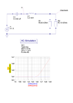
Now I think, I can: I think your unit AC current source is the culprit. See the voltages which will be created at vfeedback and in :CLR-sim.png

If your LF vin=9kV (1A into 9kΩ), and your magnitude curve shows 20log(vref/vin) = -100dB , then your (LF) vref=90mV .

I guess current stimulus doesn't work correctly here. You better stimulate with a voltage source. It's even easier to use ADE's STB (stability) analysis. Instead of your LC feedback break, just insert an iprobe, this will guarantee correct input biasing and stimulus.
 
I understand, that the stimulation is a 1V AC voltage, injected by the 100 u capacitor, which would be O.K. I rather think, that the problem is in uncorrect bias, as said by steadymind.
 
Hi All,

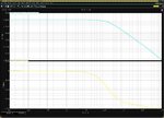
Thank you for your valuable feedback. Indeed as mentioned by steadymind and FvM, the culprit is due to incorrect bias because of pwl source is used to supply (2.5V) for the error amplifier. I should be using dc source instead. Now I can get correct loop gain (39dB) and phase margin (55Deg) from my simulation (see attachment). I used big inductance (10kH) for this simulation.

I have clicked on the help me button :)

sj
 

Attachments

  • SimResult9.jpeg
    SimResult9.jpeg
    363.7 KB · Views: 161

Status
Not open for further replies.

Part and Inventory Search

Welcome to EDABoard.com

Sponsor

Back
Top