Continue to Site

Welcome to EDAboard.com

Welcome to our site! EDAboard.com is an international Electronics Discussion Forum focused on EDA software, circuits, schematics, books, theory, papers, asic, pld, 8051, DSP, Network, RF, Analog Design, PCB, Service Manuals... and a whole lot more! To participate you need to register. Registration is free. Click here to register now.

Wein bridge oscillator again...

Status
Not open for further replies.

ccchang

Junior Member level 2
Joined
Nov 14, 2007
Messages
21
Helped
1
Reputation
2
Reaction score
1
Trophy points
1,283
Location
Penang Island, Malaysia
Visit site
Activity points
1,481
Hi

I am testing wein bridge oscillator and I looking to make it work. I have study the page below, but there are some concept i do not understand. Hope some can give a guide.


I attach a schematic a wein bridge oscillator with a single supply. But as mention in the post above, node A in the schematic can be consider as a virtual ground for the oscillator, am I right ? The wein oscillator also symmetrically biased.
So can this wein oscillator work ?

If I put my oscilloscope probe to the output and the ground the Node A. I should see a sine wave oscillates at center 0V, right ?

Thanks. Surely I can learn a lot from you all. Best wish to all E&E experts.

ccchang
 

You can create virtual ground by dividing voltage with 2 resistors and that's fine, but as far as your circuit is concerned you've got everything up-side-down ..
Compare your circuit with the attached (the second opamp provides virtual ground as the voltage divider in your circuit)
then re-wire yours and try again ..

IanP
:cry:
 

    ccchang

    Points: 2
    Helpful Answer Positive Rating
Hi

Thanks you IanP. I get the circuit working perfectly. Below is the final circuit that work for me with Vpeak-peak 10V.

However, I can I modify the wein-bridge oscillator into single resistor tuning oscillator ? I do not want use to stereo potentialmeter to achieve the tunable frequency oscillator. Really wondering is there a way to achieve that ?

Thanks. All the best !
 

Hi CCCHANG,

here are two links which could be interesting for you:

1.) WIEN oscillator with single supply and only one opamp:

**broken link removed**

2.) WIEN oscillator with single-resistor control of the frequency (however for dual supply); perhaps you can combine both principles?

**broken link removed**

Comment: I know that in several books and articles this oscillator type is called "WEIN"; however, the correct name is "WIEN" oscillator.
 

Hi

I have tried on the suggested single resistor tuning wien oscillator with split supply. I run the simulation, it seen can be done.
Practically we can get the sine wave, however when the resistor is tuned, the signal amplitude decrease and the frequency decrease. And also the tuning range is pretty small.

May I ask, if i implement a sine wave oscillator by filtering a triangular-wave or square-wave, would it be easier compare using a wien bridge ? But for my understand, if we implement in this way, we need a pretty good filter.

There are a lot way to generate sine-wave. What is the best way to implement an oscillator with below requirement ?
1.) RC only (ignore L)
2.) Single resistor tuning
3.) 10Hz-100KHz

Thanks.

CCChang
 

In case you don't have very strong distortion requirements, I think the following approach can be recommended to you:
* Use a two-opamp circuit (based on the relaxation principle) to produce a good triangle wave. The repetition rate (I avoid the term "frequency") could be tuned with one resistor.
* Use a waveform shaper to transfer the triangle into a sinusoidal signal. This shaper can be realized by a classical differential BJT amplifier (long tailed pair). For a peak amplitude of 80 mV the THD at the output will be app. only 1.3%.

By the way, there a many sinusoidal oscillating circuits, but it's rather hard to find one with single resitor tuning. If you like, I can give you some references.
 
Single resistor tuning and 1:10000 frequency range can be at best achieved with a function generator approach, not with a linear oscillator,
that would have a √R tuning characteristic. You still have the problem of a very bad tuning resolution due to the large resistance ratio. But you
did neither specify intended frequency accuray nor sine signal quality, so it's difficult to make detailed suggestions.
 

ccchang said:
Yes. I would love to have the reference. Thanks.

* Shen Juan Lio, Jiann Horng Tsay: Single-resistance-controlled sinusoidal oscillator using current-feedback amplifiers, Int. Journal of electronics 1996, vol 80, No. 5, pp 661-664

* P.A. Martinez, J. Sabadell, C. Aldea: Grounded resistor controlled sinusoidal oscillator using CFOAs, Electronics letters, Vol 33, No. 5, 27th Febr. 1997

Comment: Both articles are based on the AD844 opamp which, indeed, is a CFA. However, the AD844 is the only CFA which can be used also as a current conveyor (CC).
And you must know, that the circuits proposed use the AD844 as CC.
Therefore, these circuits can be realized with the AD844 only and NOT with any other CFA (as the title may suggest).
 

Thank you pointing to the interesting circuit concept. As assumed, the feasible frequency ratio is however limited by the f ~ 1/√R
characteristic, in contrast to a dual resistor tuned linear oscillator or filter that achieves f ~ 1/R.
 

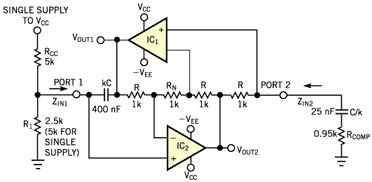
If somebody is interested in a harmonic oscillator with excellent properties, here is the circuit called "GIC resonator", see pdf attachement.
It is based on the most powerful opamp combination (GIC) and can be tuned - without touchung the oscillation condition - with one grounded resistor only (which could be replaced by a FET, for example).
It uses 3 equal valued resistors R2=R3=R4=R and two equal capacitors C1=C5=C.
In this case, the oscillation frequency is

Fo=1/2*Pi*C*sqrt(R*R6).

Fo is tuned by R6. R1 and R0 are for loss compensation with R1/R0≈0.9...0.95.

Another interesting property: It needs no amplitude stabilization circuitry as the output at A1 is a filtered version of A2 (which exhibits soft clipping).
 
Thanks for all the heartwarming reply and help.

Basically I had been assigned to implement a sine wave generator to do burn-in test for a analog chip. Therefore generated sine wave with 5% THD is acceptable.

Hi FvM, I would like to know what is function generator approach ? Either it is using DDS (direct digital synthesis) or just use classic way of convert square to sine ?

Hi LvW,
I have tested with the GIC circuit, but does not seen working to me. Therefore I tried the original GIC circuit from EDN (figure below).
99_1274687876.gif

It is amazing, however there are 4 small deadband around a cycle. Still figure out how to eliminate the deadband. Is the compensation resistor R1 and R0 is used for the purpose ?

Hope you do not mind if I ask what is amplitude stabilization ? Is that means
A.) when I shift from one frequency to another the signal amplitude may vary therefore AGC is around or
B.) at single frequency, the signal amplitude may vary, therefore AGC is around ?

**From what i observe from wien-bridge and the GIC, the signal amplitude always changing when moving from one frequency to another,.

Thanks again.
With Best wish
--ccchang
 

Function generator approach means triangular to sine designs.

I have tested with the GIC circuit, but does not seen working to me. Therefore I tried the original GIC circuit from EDN
??? Both circuits are identical.

P.S.:
there are 4 small deadband around a cycle
What do you mean exactly?. With compensation factor 0.95, the circuit shows some distortions, also at the low-pass filtered output.
You may want to increase the factor to e.g. 0.99, but then the circuit is possibly not working in a wider frequency range.

Apart from distortions introduced by voltage clipping, you may also experience slew-rate or output current limitations, depending on the
selected OP and resistance level.
 

Hi CCChang,

since the "original GIC circuit" from EDN was a design idea contribution from my side, I like to give some explanations and corrections to the circuit (all part names as in EDN):
(1) Corrections: In my original contribution there were two examples with different dimensioning (showing the influence of opamp limitations and slew rate effects).
Unfortunately, EDN editors have mixed it in order to publish only one circuit diagram. Therefore, the following corrections:
- The most left resistor is Ro (instead of R1). Its value R=2.5k for dual supply without Rcc (Rcc>>infinite).
- Equal capacitors C=100 nF (not two different caps).
In this case, you get a good sinewave at out1 with a frequency according to the given formula of app. Fo=1kHz.

(2) Explanations:
For ideal opamps Rn=Rcomp=0. Because of real opamp losses, a small negative resistance is necessary which can be realized with Rn=10...50 ohms.
However, because of several reasons (for example: diodes across Rn for further THD improvement) it is better to overcompensate with a larger Rn and to add the resistor Rcomp with the goal to make the difference Rn-Rcomp=10...50 ohms.
The main advantage of the circuit is the following: Because the GIC block is the most powerful opamp combination - as far as limitations due to the restricted opamp bandwidth are concerned - the frequency error caused by real opamp properties is minimized.

(3) For single supply: Replace Ro=2.5k with a voltage divider of two equal resistors, each with 5k, and connect the upper one as shown with the supply voltage.
_____________
I would be happy if you could communicate that it works (hopefully).
Thanks, regards
LvW
 

Hi

For the GIC, everything is look fine except I keep getting this deadband/plateau. (Figure below) How can I fix that ? Could it be coming from Op Amp offset ? I only have LM324 to implement the oscillator.

Best Regards,
--ccchang
 
ccchang said:
Hi

For the GIC, everything is look fine except I keep getting this deadband/plateau. (Figure below) How can I fix that ? Could it be coming from Op Amp offset ? I only have LM324 to implement the oscillator.
Best Regards,
--ccchang

Measured or simulated?
Single or dual supply?
Values for Rn and Rcomp?
Try Rcomp=0 and Rn increasing from 1 ohm to app. 50 ohms.
 

It's crossover distortions, normal behaviour of LM324 class-B output stage. Use a regular OP instead.

I notice, that you have requested a frequency range up to 100 kHz. It's illusional with LM324.

P.S.: For low frequencies, you can force LM324 into class-A operation by a sufficient low pull-up resistor.
 
FvM said:
It's crossover distortions, normal behaviour of LM324 class-B output stage. Use a regular OP instead.

Ohh yes - I have overlooked that ccchang is going to use the old LM324 with these properties.
 

Hi LvW and FvM

Thanks you very much for the enthusiastic guide.

Measured or simulated?
Single or dual supply?

**I measured using oscilloscope.
**It is dual supply.

Since it is the mistake to use LM324. Hence can you help to recommend other OP suitable to meet this spec ? How can we know from datasheet that an OP has class A or class B output stage ?

Thanks and best regards,
--ccchang
 

Status
Not open for further replies.

Similar threads

Part and Inventory Search

Welcome to EDABoard.com

Sponsor

Back
Top