Continue to Site

Welcome to EDAboard.com

Welcome to our site! EDAboard.com is an international Electronics Discussion Forum focused on EDA software, circuits, schematics, books, theory, papers, asic, pld, 8051, DSP, Network, RF, Analog Design, PCB, Service Manuals... and a whole lot more! To participate you need to register. Registration is free. Click here to register now.

Transmitter power vs distance

Status
Not open for further replies.

ashokone

Member level 3
Member level 3
Joined
Sep 30, 2009
Messages
56
Helped
1
Reputation
2
Reaction score
1
Trophy points
1,288
Location
banglore
Activity points
1,659
Signal to be modulated and it is passed through the channel. Then plotting power vs distance

Along with the above result different signal should be modulated and it is passed through the channel with different transmitter position..

finally plotting the result of all the signal with different transmitter position,plotting the power vs distance.

how to do this in matlab

plz help
 

Try better a real experiment. You will be surprised how reality differs from models!
 

Signal to be modulated and it is passed through the channel. Then plotting power vs distance
Along with the above result different signal should be modulated and it is passed through the channel with different transmitter position..
finally plotting the result of all the signal with different transmitter position,plotting the power vs distance.
how to do this in matlab
plz help

is this through air ? waveguide ? coax ? some other medium ?

assuming its for air (free space)...
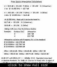
here's a file I did for my microwave pathloss talks with the formula for working out losses at various freqs


Dave
 
Hi, Dave,

what's your theory for free space? In microwave point to point, usually at 10GHz, the transmitter output power is +20dBm. Assume the antenna gain is 20dB, so the receive power is +20+20+20-112=-52dBm at only 1Km, that sounds a little small. Because at this situation, the receiver power is greater than -40dBm actually.
 

what's your theory for free space?
The -112 dB free space attenuation is obviously the result of Friis equation. I don't see a chance to cheat it, respectively get less attenuation in case of your microwave example. You can check it with any RF text book.
 
Sorry, I estimate the antenna gain errorly. For 10G, with 1M diameter antenna, the gain=4*Pi*S/(lamda^2)=40dB. So for 10G, the rx level is +20+40+40-112=-12dBm for 1Km.
Dave is right.
 

Hi, Dave,

what's your theory for free space? In microwave point to point, usually at 10GHz, the transmitter output power is +20dBm. Assume the antenna gain is 20dB, so the receive power is +20+20+20-112=-52dBm at only 1Km, that sounds a little small. Because at this situation, the receiver power is greater than -40dBm actually.

Hey Tony
happy new year :)

they are the standard free space cals (formula) used in multiple textbooks
with that formula you can work out the 1km (1mile) path loss at a given freq and as said in the attachment you add 6dB every time you double the distance....
at that point it is power irrelevent, those free space losses are then applied to whatever power levels, antenna gains, cable losses etc etc you are using to come up with an overall signal level in dB over a given path

it works and is pretty accurate when applied to real situations
I do a lot of work on 1GHz through to 24GHz. Biff mentioned one program used, I haven't tried it, I personally use UKWtools for doing pathloss calcs, there are a number of others

Cheers
Dave

PS .... yes forget about antenna gains transmitter power etc thats comes next
the formulas just give you the Path Loss for a given distance at a given freq :)
 
Last edited:
Status
Not open for further replies.

Part and Inventory Search

Welcome to EDABoard.com

Sponsor

Back
Top