Continue to Site

Welcome to EDAboard.com

Welcome to our site! EDAboard.com is an international Electronics Discussion Forum focused on EDA software, circuits, schematics, books, theory, papers, asic, pld, 8051, DSP, Network, RF, Analog Design, PCB, Service Manuals... and a whole lot more! To participate you need to register. Registration is free. Click here to register now.

[SOLVED] 16F887 with LM35DZ (measurement of positive temp only)

Status
Not open for further replies.

Eric_O

Advanced Member level 4
Full Member level 1
Joined
May 31, 2020
Messages
107
Helped
0
Reputation
0
Reaction score
0
Trophy points
16
Activity points
1,024
When measuring room temperature (approximatively between 21°C to 25°C) with PIC 16F887 and LM35DZ, LCD displays a room temperature of 100°C when room temperature is 21°C.

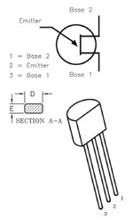
LM35 GND (pin 3) : connected to GND of MCU.
LM35 output (pin 2) : connected to ADC 3 of MCU and also to VCC thru a 2.2 K resistor.
LM35 output (pin 1) : not connected (instead of connected to VCC in some cases)

Regarding the datasheet of LM35 I wrote the code as follow and respected the math formulas.

Code:
void main()
{
 PORTB = 0;                                                 // Initialisation du PORT B à 0.
 PORTC = 0;                                                 // Initialisation du PORT C à 0.
 PORTD = 0;                                                 // Initialisation du PORT D à 0.

 ANSEL = 0b00001000;                                        // b3 = 1 (ANS3) : sets pin 5 (AN3) as analog input.
 ANSELH = 0b00000000;

 TRISB = 0b00000000;                                        // PORT B : b0 à b7 configurés en sortie.
 TRISC = 0b00000000;                                        // PORT C : b0 à b7 configurés en sortie.
 TRISD = 0b00000000;                                        // PORT D : b0 à b7 configurés en sortie.

 C1ON_bit = 0;                                              // CMC1CON register > b7 > C1ON bit = 0 > Disable comparator 1.
 C2ON_bit = 0;                                              // CMC2CON register > b7 > C1ON bit = 0 > Disable comparator 2.

 SCS_bit = 0;                                               // OSCCON register > b0 > SCS bit = 0 > External oscillator (quartz) is used as a clock source.

 LCD_Init_v4 (void);

 pointeur_de_char = &texte[0];                              // pointeur_de_char pointe sur le premier élément du tableau "texte", soit texte[0].
                                                            // Autrement dit, pointeur_de_char contient l'adresse (&) de texte[0].
 do
  {
   float adc;
   float volt, temp;

   char txt[13];

   ADC_initialization();

   TRISD = 0x00;

    while(1)
    {
     adc = (ADC_read(3));                                   // Reads analog values.
     volt = adc * 4.88281;                                  // Converts it into the voltage.
     temp = volt / 10.0;                                    // Gets the temperature values.
     temp = temp - 273;                                     // Converts Farenheit to Celcius.

     StrConstRamCpy(pointeur_de_char, "Temperature ...  "); // OK.
     LCD_Write_String_At(0, 0, pointeur_de_char);           // OK. Voir dans void LCD_Write_String(char *msg), le while(*(msg + k) > 0).

     float2ascii_v2(temp, &txt[0], 2);

     LCD_Write_String_At(1, 0, &txt[0]);                    // Write txt in 2nd row, starting at 1st digit.
     LCD_Write_String_At(1, 13, " °C");                     // Write " °C" in 2nd row, starting at 14th digit.

     delay_ms(3000);
    }
  }
 while(1);
}

Could somebody explain me why the displayed temperature is so inconsistent ?

Thanks !
 

LM35 GND (pin 3) : connected to GND of MCU.
LM35 output (pin 2) : connected to ADC 3 of MCU and also to VCC thru a 2.2 K resistor.
LM35 output (pin 1) : not connected (instead of connected to VCC in some cases)
Definitely wrong. No idea what you want to achieve.

1691504784440.png


temp = temp - 273; // Converts Farenheit to Celcius.
Also wrong. LM35 gives °C output without substracting a value.
 

Definitely wrong. No idea what you want to achieve.

View attachment 184288


Also wrong. LM35 gives °C output without substracting a value.
Thank you very much ! 🙏🏻
Some websites of electronics show wrong codes and schematics 😡.
When in doubt, it seemed to me to check in the reference document, the data sheet 😕.
You’re wright.
Many thanks 🙏🏻
Hope, switching pins 1 and 3 didn’t destroy the sensor inside ? 🤔
 

Attachments

  • 1F5EC2B0-AA30-4954-B6D5-E518FA40149F.jpeg
    1F5EC2B0-AA30-4954-B6D5-E518FA40149F.jpeg
    54.2 KB · Views: 137
  • A3DAE95F-5A08-47E5-9E13-07487FC28D4A.jpeg
    A3DAE95F-5A08-47E5-9E13-07487FC28D4A.jpeg
    76.5 KB · Views: 123

When in doubt, it seemed to me to check in the reference document, the data sheet
I use the datasheet in first place, then application notes provided by the manufacturer.
Then maybe other documents.

Klaus
 
A bit off track, but I would try very hard to not use floating point on these small MCUs. They have to do most integer arithmetic via runtime functions and they are generally fairly slow. Fixed point integer arithmetic is the way to go. At the last step you can put the decimal point in the right place as you are generating the ASCII characters for the display.
Having said that, as you delay for 3 seconds between samples that is probably not an issue in this case.
Also you might be getting some variation in the value because of 'noise' on the bottom few bits of the ADC value. If the situation allows, I like to sample the ADC repeatedly (often a power of 2 times) and sum the values before dividing by the number of samples (if a power of 2 is used then this becomes a right-shift).
Susan
 

Hi,

I agree with Susan.
And I usually go a step further than her recommendation.
(This does not mean that Susan´s advice is bad .. it´s just my way to do it).

I usuallly use filters accoding sampling rate / nyquist and mains frequency.

This means I install analog filters that suppress noise beyond nyquist frequency and I do sampling with a fixed, known sampling frequency. (Interrupt based or hardware timed) Then I often apply filters on the digital side. (simplest: averaging). When averaging I usually do this in multiples of mains period time, so that mains frequency residuals cancel out.

This sounds very sophisticated, but indeed it doesn´t take much time.
Example:
Let´s say you have 50Hz mains, then using 1600 Hz sampling frequency and storing 160 sampling data via DMA .... does not take any processing power so far!!! (all this can be configured using STM32 cube )
(you are free to adjust sampling rate and averaging number on your needs)
In an ISR now you can put code to just add up those sample values and store the result in a global variable. This takes just a couple of microseconds every 100ms. Ignorable less than 0.1% of processing power. This way the value gets updated every 100ms automatically, is very relaible, and can be accessed in software without any delay.
Once you have written the tiny ISR averaging code (reusable in any other project), you may just forget about it. It won´t hurt ..and it won´t have influence on your other code (besides only 99.9... % remaining processing power)

Again: It´s just may way, since I´m somehow an enthusiast on signal processing...

Klaus
 

I use the datasheet in first place, then application notes provided by the manufacturer.
Then maybe other documents.

Klaus
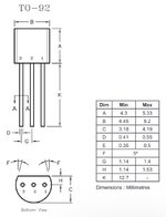
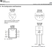
Finally it is very confusing, because datasheet (most popular is Texas Instruments or National Conductor) never indicate pinout numbers.

But, when searching "LM35DZ pinout" on Google, or Bing, I think I was right.

😕

Hope without the wrong line temp = temp - 273; values on LCD will be more consistent.

Will try.
 

Attachments

  • LM35 - pinout.jpg
    LM35 - pinout.jpg
    359.1 KB · Views: 128

Finally it is very confusing, because datasheet (most popular is Texas Instruments or National Conductor) never indicate pinout numbers.
Hi,

I don´t kow what you are talking about.

TI datasheet, page #5
National semiconductor page #2

I would have been very surprised if they were not providing such basic informations.
I mean, they want to sell these devices to earn money, so it would be counter productive...

Klaus
 

Pin numbers are just convention, the actual pin assignment is clearly given in the datasheet, see post #2. In so far I don't understand your problem.
 

Hi,

I don´t kow what you are talking about.

TI datasheet, page #5
National semiconductor page #2

I would have been very surprised if they were not providing such basic informations.
I mean, they want to sell these devices to earn money, so it would be counter productive...

Klaus
Yes it is true. A recent TI datasheet shows, at chapter 5 the pinout with pin number & name.
Thanks.
PS :
Concerning negative values, I guess there's a special wiring with LM35 when using only a VCC of 5 V ?
 

Attachments

  • LM35 - pinout - 2.jpg
    LM35 - pinout - 2.jpg
    167.3 KB · Views: 136

Concerning negative values, I guess there's a special wiring with LM35 when using only a VCC of 5 V ?
yes, there are several examples on the datasheet.
the easiest IMO, is the two diodes and pull down resistor
Screenshot from 2023-08-16 13-15-06.png

just note that for a correct measurement, you need to read both the VOUT and the GND of the LM35 (that goes to the diodes). but if needed you can omit the GND measurement and calculate with a fixed value.
 

    Eric_O

    Points: 2
    Helpful Answer Positive Rating
yes, there are several examples on the datasheet.
the easiest IMO, is the two diodes and pull down resistor
View attachment 184431
just note that for a correct measurement, you need to read both the VOUT and the GND of the LM35 (that goes to the diodes). but if needed you can omit the GND measurement and calculate with a fixed value.
Thanks for schematics.
You would have an example of a code in MikroC.
I guess will need another ADC chanel ?
Thanks !
Eric
 

yes, there are several examples on the datasheet.
the easiest IMO, is the two diodes and pull down resistor
View attachment 184431
just note that for a correct measurement, you need to read both the VOUT and the GND of the LM35 (that goes to the diodes). but if needed you can omit the GND measurement and calculate with a fixed value.
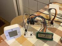
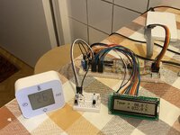
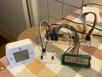
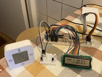
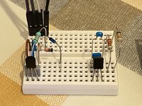
Thanks for schematics. I added also a 150 nF capacitor between V+ (pin 1) and GND (pin 3) of LM35DZ. But with the following part of my code, with ADC channels 3 and channels 4, even I have a wrong positive temperature (see photos).
Code:
....
  voltage_at_Vout_pin = ADC_Read(3);                                 // Reads analog voltage at Vout pin of LM35DZ.
  voltage_at_GND_pin = ADC_Read(4);                                  // Reads analog voltage at GND pin of LM35DZ.
 
  temp_Celsius = (voltage_at_Vout_pin - voltage_at_GND_pin) * 4.888; // Reads analog voltage and converts it to Celsius degrees (4.888 = 5000 mV / 1023). 5000 mV = 5V = VCC of MCU.

  temp_Celsius = temp_Celsius / 10;                                  // With LM35, each 10 mV output correspond to 1°C.
  temp_Kelvin = (temp_Celsius * 9/5) + 32;                           // Converts Celsius degrees to Kelvin degrees.
  ...

Have no ideas why temperature displayed is so different with room temperature. Even after I changed LM35DZ.

🤔
 

Attachments

  • 5B8C8743-CA18-493A-9F02-8486C5BA89F9.jpeg
    5B8C8743-CA18-493A-9F02-8486C5BA89F9.jpeg
    3.5 MB · Views: 131
  • 8B389249-A4A0-475A-97E4-04153FB528AB.jpeg
    8B389249-A4A0-475A-97E4-04153FB528AB.jpeg
    3.5 MB · Views: 149
  • 8E5D759C-9D69-43EB-A540-AA91FD11F499.jpeg
    8E5D759C-9D69-43EB-A540-AA91FD11F499.jpeg
    3.4 MB · Views: 110
  • CD73BA7A-FD3C-4B19-868C-7B34B2B0CC50.jpeg
    CD73BA7A-FD3C-4B19-868C-7B34B2B0CC50.jpeg
    3.3 MB · Views: 111
  • 64D6015D-1660-42D3-AA92-5F5AE5689D59.jpeg
    64D6015D-1660-42D3-AA92-5F5AE5689D59.jpeg
    2.2 MB · Views: 166

Please tell us the types of variables you are using (char, int, float etc.).
This could simply be a problem of storing in the wrong kind of variable or missing an essential typecast.

All the "Voltage_at_" variables should be integers and all the "temp_" ones should be floats.

Brian.
 

A couple of things straight off (even without knowing the data types - although that really is important!).
You are using a very small MCU so floating point maths is all done via library code that is slow and takes up a lot of space. Try to use scaled integers where ever possible.
What are the values you are getting from the ADC?
Also the "9/5" is probably going to cause a problem. It could well be that it is being calculated by the compiler (or the run-time - it really doesn't matter) to be 1 as it will be seeing this an integer division.
Susan
 

Please tell us the types of variables you are using (char, int, float etc.).
This could simply be a problem of storing in the wrong kind of variable or missing an essential typecast.

All the "Voltage_at_" variables should be integers and all the "temp_" ones should be floats.

Brian.
Dear Brian,
Here under my code ... While running, temperature displayed on LCD start from a negative value a increase to 3 or 4°C ... No more. While room temp is around 20°C now.
Code:
void main()
{
 PORTB = 0;                                                 // Initialisation du PORT B à 0.
 PORTC = 0;                                                 // Initialisation du PORT C à 0.
 PORTD = 0;                                                 // Initialisation du PORT D à 0.

 ANSEL = 0b00011000;                                        // b3 = 1 (ANS3) : sets pin 5 (AN3) as analog input.
                                                            // b4 = 1 (ANS4) : sets pin 7 (AN4) as analog input.
 //Or
 //ANSEL = 24;
 ANSELH = 0b00000000;

 TRISB = 0b00000000;                                        // PORT B : b0 à b7 configurés en sortie.
 TRISC = 0b00000000;                                        // PORT C : b0 à b7 configurés en sortie.
 TRISD = 0b00000000;                                        // PORT D : b0 à b7 configurés en sortie.

 C1ON_bit = 0;                                              // CMC1CON register > b7 > C1ON bit = 0 > Disable comparator 1.
 C2ON_bit = 0;                                              // CMC2CON register > b7 > C1ON bit = 0 > Disable comparator 2.

 SCS_bit = 0;                                               // OSCCON register > b0 > SCS bit = 0 > External oscillator (quartz) is used as a clock source.

 LCD_Init_v4 (void);

 pointeur_de_char = &texte[0];                              // pointeur_de_char pointe sur le premier élément du tableau "texte", soit texte[0].
                                                            // Autrement dit, pointeur_de_char contient l'adresse (&) de texte[0].
 do
  {
   int voltage_at_Vout_pin, voltage_at_GND_pin;
   float temp;

   char txt[13];

   ADC_initialization();

   TRISD = 0x00;

    while(1)
    {
     voltage_at_Vout_pin = ADC_read(3);                           // Reads analog voltage at Vout pin of LM35DZ.
     voltage_at_GND_pin = ADC_read(4);                            // Reads analog voltage at GND pin of LM35DZ.

     temp = (voltage_at_Vout_pin - voltage_at_GND_pin) * 4.888;   // Reads analog voltage and converts it to Celsius degrees (4.888 = 5000 mV / 1023). 5000 mV = 5V = VCC of MCU.
     temp = temp / 10;                                            // With LM35, each 10 mV output correspond to 1°C.

     StrConstRamCpy(pointeur_de_char, "Temperature ...  ");       // OK.
     LCD_Write_String_At(0, 0, pointeur_de_char);                 // OK. Voir dans void LCD_Write_String(char *msg), le while(*(msg + k) > 0).

     //float2ascii_v1(temp, &txt[0], 2);
     float2ascii_v2(temp, &txt[0], 2);

     LCD_Write_String_At(1, 0, &txt[0]);                          // Write txt in 2nd row, starting at 1st digit.
     LCD_Write_String_At(1, 13, " °C");                           // Write " °C" in 2nd row, starting at 14th digit.

     delay_ms(3000);
    }
  }
 while(1);
}

Thanks for enlighten me.

Eric
 

A couple of things straight off (even without knowing the data types - although that really is important!).
You are using a very small MCU so floating point maths is all done via library code that is slow and takes up a lot of space. Try to use scaled integers where ever possible.
What are the values you are getting from the ADC?
Also the "9/5" is probably going to cause a problem. It could well be that it is being calculated by the compiler (or the run-time - it really doesn't matter) to be 1 as it will be seeing this an integer division.
Susan
Merci Susan.
For next experiment I will plan to switch to PIC 18F, 18F4550 or 18F46K2X.
Which one you would recommend me ?
🤔
Thanks 🙏🏻
 

What is the code in 'ADC_initialization()' as that will determine how the values are being represented in the 'Voltage_at_...' variables. Ditto the code in 'ADC_read()'.
Have you tried to debug the code?
In particular what are the values that you have in the 'Voltage_at_...' variables? If they are not right then your calculations are somewhat meaningless.
Susan
 

Status
Not open for further replies.

Similar threads

Part and Inventory Search

Welcome to EDABoard.com

Sponsor

Back
Top