rasterman101
Newbie level 3

I am coding a PWM to a H-Bridge using a shift register. The code to the shift register works but when I look at my PWM, it appears that a logic gate is pulling down the signal on PORTC.RC3. I remove the wire from PORTC.RC3 to a logic gate, the clock signal is fine. Place the wire on the logic gate, the clock starts and stops. It appears that the signal on PORTC.RC3 is being loaded down by the logic gate.
Do I need a pull-up resistor on a transistor to drive the logic gate using a 16f690? I have swapped out the logic gate with a new gate.
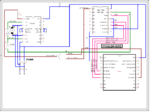
Schematic
Do I need a pull-up resistor on a transistor to drive the logic gate using a 16f690? I have swapped out the logic gate with a new gate.
Code:
// 16f690
// 74HC08
// H-Bridge
#include "shift_data_in.h"        // This clocks in data to the shift register
#include "output_info.h"          // This outputs the data on the shift register

void main(){
   CM1CON0.C1ON = 0x00;           // disable comparitor
   CM2CON0.C2ON = 0x00;           // disable the other comparator

   TRISC   = 0x00;                // Set all of PORTC as I/O
   PORTC = 0;                      // Starts the shift register at zero

   while(1){

// Turn right motor on
// Shift register info passing
        DS_Data_IN(right_FW);                  // Sends info over to shift register
        Delay_ms(100);
        output_data();                             // Outputs the data in the shift register

// My PWM worked using the libraries
// as well as coding the PWM
// This is just for testing purposes

        for(y_in = 0; y_in <= 1000; ++y_in){
            RC3_bit = 1;
            Delay_ms(2);
            RC3_bit = 0;
            Delay_ms(2);
           }
        }
   }  // END WHILE
}  // END MAIN
Schematic

