Continue to Site

Welcome to EDAboard.com

Welcome to our site! EDAboard.com is an international Electronics Discussion Forum focused on EDA software, circuits, schematics, books, theory, papers, asic, pld, 8051, DSP, Network, RF, Analog Design, PCB, Service Manuals... and a whole lot more! To participate you need to register. Registration is free. Click here to register now.

16-stage stereo peak hold/decay VU meter (mikroC, PIC)

Status
Not open for further replies.

zuisti

Advanced Member level 1
Joined
Jul 2, 2004
Messages
479
Helped
188
Reputation
376
Reaction score
183
Trophy points
1,323
Location
Hungary
Activity points
3,319
Compiler: mikroC Pro for PIC v6.01
Proteus-only projects, using 2x16 LEDs and/or a 4x20 LCD

I made four projects that are in different folders:
16F88_LED............18-pin PIC, 2x16 leds, exact timed multiplexing
44K22_LED............40-pin PIC, non-multiplexed (direct) led control
16F684_LCD..........14-pin PIC, 4x20 LCD
44K22_LCD-LED.....LCD and LEDs, both at a time (see the video)

Common features:
- runtime switchable characteristic:
. lin: 6 to 100 %
. log: -36 to +12 dB, 3 dB/step
- a real wav audio file is used as an input (cannot be heard in Proteus)
- adjustable input LEVEL (sensitivity)
- 250 Hz refresh rate (4 ms)

LED bargraph:
- level-dependend LED colours (12 green, 3 yellow, 1 red; a total of 16 leds)

LCD:
- 16 chars wide bargraph using User Defined Chars (UDCs)
- always visible scale-line (part of all UDCs)
- displayed audio channel (R and L) and current unit (% or dB)
- displayed scale values (second line)
- level-dependend shapes (UDCs) to imitate the different led colours
- runtime switchable 3 different sets of shapes (UDCs): three diff. modes
- the first line shows the current characteristic (lin-log) and mode (0-1-2)

For more description see the included "README_FIRST.TXT" (and the source) files.
--------------

A video to show how to works the simulated LED and LCD VU meter
(the "44K22_LCD-LED" project was used, its circuit is attached as a GIF):
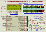

44K22_Lcd-Led_VU.gif

© Istvan K (zuisti), 2017
 

Attachments

  • VUprojs_up.rar
    6.2 MB · Views: 970
So far 14 downloads and no any feedback (and no any thankyou :-( ), although I worked hard on it.
I would like to thank someone for a better (more effective) peak-hold algorithm than what I wrote and published.

Since then, I've made a 'one-line' stereo VU meter project, which only uses the bottom line of a 16x2 LCD.
The picture of the working simulation is attached, but I do not want to publish the entire project, sorry.
Istvan
 

Attachments

  • 16F684_oneline_VU.gif
    16F684_oneline_VU.gif
    35.4 KB · Views: 1,244

Very nice project indeed! It shows the amount of effort you have done.

I love audio bargraph VU meters, building my first one back in the mid 1970s. But I'm not a good programmer to even attempt half what you have done here with a microcontroller.

I would give you a little advise, though. If you use a full wave rectifier with an opamp input, the display will respond better. If you are interested I can give you the details..
 

Hi schmitt trigger!
I think you are more of an 'analogue' man (nomen est omen ;-)). For a long time I was also like you, too ...
Thank you for your kind words.

I love audio bargraph VU meters, building my first one back in the mid 1970s
Welcome to the club (although I am only 73 years old :lol:).
At this time I also built a VU meter, first with discrete transistors, but a bit later I used TTL ICs also (Texas SN74 series, oh old good times).

If you use a full wave rectifier with an opamp input, the display will respond better
Thank you for your advice, you are absolutely right. However, as I wrote, in Proteus that was not necessary.
From my "README_FIRST.TXT" file:
Since my projects are 'Proteus-only', some (in the reality needed) things are
missed (because they are unnecessary in Proteus):
....
- real analog input stages (eg amplifiers, better filters, protections)
....

And yes, a full wave rectifier sure would be better.

Thanks again. Kind regards,
Istvan (alias zuisti, an old - already retired - engineer from Hungary)
 

Hi friend zuisti, I commented that this is why I can see a great design, I have been looking for a circuit like this to use it in a control of tones that arme, although I have a vumetro with integrated circuit, I am always interested in another with pic, in itself, something like the circuit you raise, allows me to say thank you for sharing something like this interesting circuit, I hope to soon armarlo and see how it performs. Good job.. Muchas Gracias desde Xalapa Veracruz México.
 

Attached the expanded and improved version 2.1

What's new ..

- Two new projects:

-- the 'one-line' stereo VU meter, in the "ONELINE" folder (see my post #2)

-- On request a 2x10 LED version, in the "16F88_2x10led" folder.


- Fixes:

-- The displaying of the text "lin/log" on the upper LCD line now changes already
at runtime too (according the jumper).

-- New, faster and smaller Lcd_Goto functions (see the "LCD_Lcd0.h").

-- Separated "poscalc.h", so it is easier to create multiple instances with
different names (and different, own static variables).


Read more in the new, improved "README_FIRST.TXT".

- Note:
To decrease the size of the uploaded RAR the "test.wav" file is missing in the
"wav" folder (it is not really compressible). Please copy from the previous RAR.
Likewise, the video (the AVI file) is also missing as it has not changed.

Greeting,
zuisti
 

Attachments

  • VUprojs_21.rar
    385.6 KB · Views: 529
Status
Not open for further replies.

Similar threads

Part and Inventory Search

Welcome to EDABoard.com

Sponsor

Back
Top