150W DC-DC step-up converter for 100W LED

Status
Not open for further replies.

Jestin_cubetech

Advanced Member level 1
Joined
Jun 24, 2012
Messages
499
Helped
76
Reputation
152
Reaction score
73
Trophy points
1,328
Visit site
Activity points
3,697


Input voltage :10-32V
Output voltage: (a) continuously adjustable (12-35V)
Output Current: 6A (MAX)
Input Current: 10A (MAX) (Please enhance heat dissipation over 10A,)
Output power: natural cooling 100W (MAX), plus fan 150W (MAX)
Easy to drive 65W 90W dual-core notebook computers, including
With a 12V battery with plain 19V 3.42A laptop module temperature of about 45 degrees
Conversion efficiency: 94% (Input 16V Output 19V 2.5A when measured) (for reference only)
Operating temperature: Industrial grade (-40 ℃ to +85 ℃) (ambient temperature exceeds 40 degrees, lower power use, or add fan)
Full load temperature rise: 45 ℃
No-load current: Typical 25mA
Short circuit protection: None (Please enter install over current protection device)
Input Reverse Polarity Protection: None, the input diode in series
Dimension: 65x 49 x 23 mm


**broken link removed**


can i use a boost converter for 100W led driving ?


thank you.
 

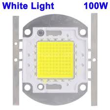
Colour Temperature (K): 5500-6500

Forward Voltage (V): 32-36

Forward Current (ma): 3500

Operating Temp: -25 ~ +85

Luminous Intensity (LM): 9000 - 11000
 

So you posted the specs of an actual product... are you trying to reverse engineer it?

Looking at your picture, it's definitely a simple CMC boost using the UC3843. So keep in mind it's restricted to the condition Vout>Vin, so its specified operating conditions aren't really true.
 

i am planning to make a LED car head light.
input voltage is 12V DC from car battery.
there is a dc-dc converter [150W dc-dc boost converter] because LED needs 32-36 V.

- - - Updated - - -


For high power LEDs I would strongly recommend getting a current regulated SMPS, rather than a voltage regulated one. Otherwise you may find that you get positive thermal feedback which ends up destroying things. Also you would need to be very careful that the electronics are capable of running continuously in automotive conditions (high ambient temperature, lots of vibrations). Personally I would steer clear of that module for automotive stuff.
 

you would need to be very careful that the electronics are capable of running continuously in automotive conditions (high ambient temperature, lots of vibrations).

The car is a hazardous environment - also the voltage varies considerably [from <11V to ~15V] wth surges and transients.

How stable is the Vout?


As an aside how will you handle the HIGH and LOW beams?
 

PWM for Dimming option.
and DC-Dc Boost converter is reliable , if Vin< Vout out put is stable.
hmm i think i need a 3A constant current source.

12v to 34V dc-dc boost -> 3A constant current source ->MOSFET PWM dimmer ->100W LED

is it correct ?
 

Usually a dc-dc booster will regulate voltage, with a limiter on current - which is fine:

dc-dc boost ------> PWM dimmer
 

Whatever amount of current you want from the 36V output, you'll need to provide 3X that from the 12V supply.

So for 100W output, your converter will need about 9A input. Even more, because (a) the coil waveform ranges above and below an average level, and (b) because of losses.

You may need to parallel 2 or more interleaved boost converters...
or you may need to chop the 12V through an H-bridge and feed it to a step-up transformer.
 

how can i operate this 100W led with minimal components and efficient.

Here is a simplest possible H-bridge configuration, driving a step-up transformer.


Where it says 'load', you would probably install a diode bridge and smoothing capacitor. That will give you 35 VDC after diode drops. So in view of that, the transformer will need an even higher windings ratio.
 
thanks BradtheRad

i have a doubt..

what about current limiting /constant current source
LED needs 3.5 A only

--------------------------------
100W LED
Forward Voltage (V): 32-36
Forward Current (ma): 3500
 

what about current limiting /constant current source
LED needs 3.5 A only

--------------------------------
100W LED
Forward Voltage (V): 32-36
Forward Current (ma): 3500

To do this you will need to install additional components.

You can adjust 'On' time of the switching devices (mosfets/transistors). Possibly install a current-sensing resistor inline with the load. Amplify the volt level across it. Have it drive an optocoupler. Create a feedback network so it alters the clock accordingly.

Or you can install current regulation at your output stage (or secondary side of the transformer).

I can't say which is easier to do, or which is safer for the LED, or which is more efficient.
 

How committed are you to this particular LED? The matrix style LED is better suited for mains power, although there are lower voltage versions available (ie 24V).

I suggest the electronics would be easier if using very high power individual LEDs in a cluster.
 

Status
Not open for further replies.

Similar threads

Cookies are required to use this site. You must accept them to continue using the site. Learn more…