Continue to Site

Welcome to EDAboard.com

Welcome to our site! EDAboard.com is an international Electronics Discussion Forum focused on EDA software, circuits, schematics, books, theory, papers, asic, pld, 8051, DSP, Network, RF, Analog Design, PCB, Service Manuals... and a whole lot more! To participate you need to register. Registration is free. Click here to register now.

Feedback problem using TL431 and opt-coupler (updated)

Status
Not open for further replies.

hsklkk

Member level 2
Member level 2
Joined
Jun 29, 2008
Messages
45
Helped
0
Reputation
0
Reaction score
0
Trophy points
1,286
Activity points
1,581
opt coupler

I use TL431 and opt-coupler for my full bridge converter feedback control, but my output voltage is about 200v, if i use voltage divider (200V to 30V for feedback), it does not work.
If vout=200V, Vcontrol drop to 15v rather than 30V
I think it needs a DC isolation, right?
Any suggestion?
 

using tl431

R11 should be connected directly to the +200V ouput. Then you calculate your R8 and R9 so as to get 20V at the output: Id=2.5V/R8. Id*(R8+R9)=200V
Set Id to about 1mA or so and then R8=2K49. R9≈200K

R11 should be chosen so as to limit the optocoupler current to safe limits. So let's ay you need a max of 10mA. then R11=200/10=20K

I would also add a 20V Zener across the TL431, because its maximum voltage reating is only about 36V.
 

tl431 feedback phase margin

Yes. it's important that the voltage at TL431 reference input doesn't depend on the LED current, so an independent supply connection for the LED is needed.
R11 should be connected directly to the +200V ouput.
Results in a too small LED current range. The suggested Z-diode can be better used to create a suitable low operating voltage for LED. To reduce the current drawn from 200V to the minimum (= LED current), a high voltage transistor can be used with the auxilary regulator.
 

design with pc817 and tl431

direct connect to 200v is no problem? since 200v is over the voltage rating of opt and tl431
can any post the improved circuit?

Added after 6 minutes:

tl431 ref needs 2.5v, why not Id=2.5V/R9?????
 

phase margin using tl431

9_1235460298.gif
 

tl431 ray ridley

how to set vout of TL431? Id=1ma then , vo of tl431=20v?

Added after 1 minutes:

FvM said:
can you design every rating for my control circuit?
Vo =200V
 

tl431 worst case

I don't know the intended LED current.
 

improved tl431

I used 4N25 for opt coupler
how's the rating of other component such as Z-diode

Added after 8 minutes:

also, is 4N25 good? if not, any suggestion?
 

tl431 tutorial

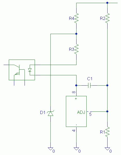
Dimensioning goes like this: Determine the photo transistor current that has to be maintained in closed loop operation. Determine the respective minimum and maximum LED current according to the optocoupler CTR. The circuit must be able to achieve the maximum LED current (+ some margin). To reduce power rating of the high voltage resistor R4, the LED current should be kept low, e.g. 2 or 5 mA. D1 voltage can be an arbitrary value between 10 and 30 V. R4 current (Vout-Vz)/R4 should be above ILED, so R4 may need 1 or 2W power rating.

As an additional remark, the Z-Diode cancels the proportional gain of TL431 circuit and modifies the frequency characteristics. It may be meaningful to add a series resistor to C1 to recreate the proportional gain respectively a zero in transfer function.
 

tl431 pc817

seems little compliated for me...
I decided R4=(200-30)/3mA=56.7K,R1=2.5K,R2=197.5K,c1=0.1u,VD1=30V, is this ok????
how to determine R3 and R in series C1?

Added after 5 minutes:

and , how to achieve the maximum LED current (+ some margin).
 

circuit connections for tl431

The required LED current depends on the dimensioning of parts around the phototransistor and the optocoupler CTR. R3 must be low enough to allow full LED current without saturation of TL431, 4.7K as in your previous circuit should be O.K. But it can be decreased to increase feedback gain. R depends on the indetended P gain, may be 10 to 20 k.
 

pc817 transfer function

The circuit as presented by FvM will work. The values you propose should also work. You do not need to worry too much about any resistor in series with the cap, as that will only add a zero to the loop. You need a slow circuit for now, to make sure you got the regulation right. Then we can talk about transient performance.

Again, the LED current must be limited. It will be limited by R3+R4, so you can select R4 so that the Zener has a low enough current through it. After all, the Zener is only there to protect the TL431. Then select R3 to limit the LED current to say 10mA or so. That means the sum of R3+R4 should be at least 200/10=20k.
On the other hand R4 may need to be much larger than that to limit the Zener current. So set R4 and then choose R3 in the order of a few kohm.

What is the value of the resistor used with the phototransistor?
 

how pc817 works with tl431

thanks for VVV and FvM very very much. I used 4N25 for my coupler, but acutally I don't know it is good or not and the design from the CTR curve....
Initially, I design IF=3mA and Ic=2.5mA then using 1K for phototransistor so that the VEAP operates at Vref/2.....
I uploaded photos for details...
4N25 data sheet
http://www.datasheetcatalog.com/datasheets_pdf/4/N/2/5/4N25.shtml
 

tl431 + pc817

Initially, I design IF=3mA and Ic=2.5mA then using 1K for phototransistor

Please consider, what happens in your design, if the phototransistor isn't able to pull down EAP to the minimum PWM ramp voltage (e.g. 0.2 V), please also assume minimum specified 4N25 CTR of 20 %.

You'll find, that an worst-case If of about 10 mA would be needed to shut down the PWM in no-load operation. Otherwise the ouput voltage must be expected to rise unregulated, possibly causing catastrophic failure. Basically, that's what my previous remark was addressd to.

Determine the respective minimum and maximum LED current according to the optocoupler CTR
Obviously, the typical Ic bias point should be shifted to a considerable lower value. Or use an optocoupler with tighter tolerances.
 

phase margin compensation using tl431

is it better if I design IF=2mA???
This is a voltage control...will it become worse in no-load operation or light load?
 

how to increase the phase margin with tl431

1)first i would like to ask how to determind operate V of TL431???depend on Id mentioned above i.e Id=1mA, then Vtl431=20v????
2)here's my design,pls check....
R1=2.5K,R2=197.5K (such that Id=1mA)
R3+R4>200/10mA=20K
R3=(30-Vf-Vmin of TL431)/2/3mA (notice:set operation point at mid dynamic V and IF=3mA)
R3=(30-1.5-2.5)/2/3mA
Vz=30V (zenser = 30V 500mW)
R4=(Vo-Vz)/10mA=17k
C1=0.1u, R5=10K
R6=500 (set Ic min is about 0.5mA and Ic max is about 10mA)
 

isolation tl431

I don't see a clear criterion to define TL431 operating voltage, however R3 modfies the regulator gain. I think that it can work, as you proposed. R4 must have at least a 2W rating. To be able to shut down the PWM in idle operation in case of minimum 20 % CTR, R6 must be dimensioned above 2.5k, very important.

I just thought of a simplification. If you omit D1 and put R3 in it's place, the proportional action of the standard (low voltage) TL431 circuit is achieved anew and R5 can be also omitted. R4/R3 is a simple voltage divider then, with a 17:3 ratio the permissible voltage range of TL431 would be kept. Can be realized as a assembly variant of the previous suggested circuit.
 

feedback tl431

1)why R6 is about 2.5K, how to determind?
2)What do you mean replace D1? use R3(two R3 in circuit)?or take it out(it seems become my very original design, it does not work)?
3)if I keep using the approach (by Z-diode), what is the good value for R5,c1,R3?
4)if i just replace R6 with 2.5K, does my design work?
 

tutorial on tl431

FvM said:
I don't see a clear criterion to define TL431 operating voltage, however R3 modfies the regulator gain. I think that it can work, as you proposed. R4 must have at least a 2W rating. To be able to shut down the PWM in idle operation in case of minimum 20 % CTR, R6 must be dimensioned above 2.5k, very important.
would it be better if I use PC817 that min CTR=80%
 

tl431 pwm

would it be better if I use PC817 that min CTR=80%
Yes. But it can work with 4N25 as well, using approriate dimensioning.[/quote]
 

Status
Not open for further replies.

Part and Inventory Search

Welcome to EDABoard.com

Sponsor

Back
Top