vwdevotee
Newbie level 4

choose which dc converter topology
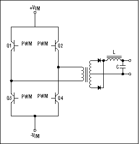
I'm looking to design a high power DC/DC converter for an electric car but I can't seem to find any websites with design equations. I was told to look at full bridge converters since I want to go from 300V to 13.8V. Looking at the topology below my question becomes how do I size the inductor and capacitor? Is it just a matter of playing with SPICE or some other software, or are there published analytical relationships? Also, and here's the really newb question, what's the "firing" order of the FETs labeled 1-4? I assume they all have the same PWM duty cycle. I'm planning on using a PIC controller for the PWM.

I'm looking to design a high power DC/DC converter for an electric car but I can't seem to find any websites with design equations. I was told to look at full bridge converters since I want to go from 300V to 13.8V. Looking at the topology below my question becomes how do I size the inductor and capacitor? Is it just a matter of playing with SPICE or some other software, or are there published analytical relationships? Also, and here's the really newb question, what's the "firing" order of the FETs labeled 1-4? I assume they all have the same PWM duty cycle. I'm planning on using a PIC controller for the PWM.


