Continue to Site

Welcome to EDAboard.com

Welcome to our site! EDAboard.com is an international Electronics Discussion Forum focused on EDA software, circuits, schematics, books, theory, papers, asic, pld, 8051, DSP, Network, RF, Analog Design, PCB, Service Manuals... and a whole lot more! To participate you need to register. Registration is free. Click here to register now.

100V 10A constant charging current circuit ?

Status
Not open for further replies.

patelvimal20

Junior Member level 3
Joined
Oct 11, 2010
Messages
27
Helped
2
Reputation
4
Reaction score
2
Trophy points
1,283
Activity points
1,463
Kindly any body share circuit of 100 VDC, 10A Constant current sourcing circuit.? Not SMPS. 100VDC line to 10A Constant current circuit.
 

MOSFET based constant current circuit.

Kindly anybody share circuit of MOSFET based constant current.?
 

Hi,

No SMPS means linear. Then expect worst case generated heat of 100V x 10A = 1000W. How do you disspate it?
Are you sure you want this?
Please give more information. Overview, diagram, values..

Klaus
 

I have big capacitor of 30mF, 250 VDC & I want it to charge at 100 VDC with 10A constant current.
What i feel is that it possible with the PNP transistor. With the use of resistor i can do it but for that requirement of resistor is higher & apart from that losses across resistor is higher.
 

HI,

To charge a capacitor to 100V you need a supply voltage HIGHER than the capacitor voltage.


Is this correct?
Capacitor: 30mF (is there a range, or fixed?)
Capacitor voltage: 0V ... 100V (voltage limited by constant current circuit?)

give values:
Supply voltage? Precise? Ripple?
Where does it come from? AC mains?

How precise do you want the 10A?
Is it a measurement device with 10.000A to measure the the capacitance, or is it just to reduce inruh current to 5..15A?

***
PNP, NPN, P-Ch, N-Ch .. doesn´t matter.

Klaus

Added:
The capacitor should be full after 300ms. Within this 300ms you have a calculable ammount of energy (heat) to dissipate.
To calculate a heat sink one needs to know how often you want to charge the capacitor. 3 times a second or once a year?

Klaus
 

Dear Klaus,

Thanks for the response & quires.

A High power 100V, 20A DC source is available. I need to charge 30mF, 250 VDC capacitor with 10A contact current circuit. Here source is 100V so capacitor is charged up to 100 VDC only. This capacitance 30mF is fixed.
Charging current 10A is not precise. it is ok for 8A or 9A or 11 A or 12 A.
This charging can be required once in a day. Minimum 7 Days i need to test.

Any more question then kindly contact again.

Regards,
Vimal
 

I see an option to use two resistors and relay.
One resistor 10 Ohm 100W charging from 0 to 70V, than relay switching on another one 3 Ohm in parallel to first one that icreasing charging current. Efficency will be poor, but you said nothing about that.
 
  • Like
Reactions: RETGT

    RETGT

    Points: 2
    Helpful Answer Positive Rating
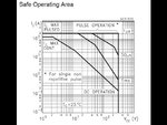
I would start to be rather concerned about second breakdown with 100v across a bipolar transistor run at high current.

safearea.jpg

This is the safe operating area curve of of a pretty large 300v 200 amp rated transistor.
Notice that at 100 volts, only a maximum of 1 amp continuous dc is allowed.
That is not a misprint, it really is only one miserable amp for a 200 amp rated device.

Check what your transistor can actually safely do.
 

Hi,

The constant current circuit will have some voltage drop. Therefore it is impossible to charge a capacitor to 100V with a 100V source.

The dissipated energy is 150Ws = 150J

The 300ms of charging time acts more as "DC" than a short "pulse". You will need huge transistors with 1kW peak heat dissipation capability, and a heat sink.
It doesn´t need to be very big, it more acts like a heat capacitor than as a heat spreader.

The thermal capacity of aluminum is 897[1] J/(kg · K).
If we calculate with 30K of temperature rise, then ... you need about 6 gramms of aluminum. (ignoring the thermal capacity of the transistor itself)

If you calculate to charge the capacitor once a minute, then only 2.5W need to be dissipated (averaged).
If we here calculate with additional heating of 30K then you just need a 12K/W thermal resistance heatsink.

Very good thermal conductivity between transistor and heatsink is essential.

Klaus
 

ok
With the use of resistor is ok but it is lossy & not workable or i can say not preferable.
even i have also find same issue as tony mention in his reply.
Transistor have their safe operating area.

one thought i have can we use MOSFET ?
because MOSFET can easily come with higher current.
If some one have any good idea or circuit with MOSFET as constant charging, kindly share.
 

Yes a mosfet would not have that safe current restriction at high voltages problem.

I only mentioned it because you said you particularly wanted to use a bipolar transistor that you already had.

Even a mosfet is going to have to dissipate up to 1KW for a brief period, its a pretty explosive short burst of heat in a very small volume of silicon.
I think many of us here might be reluctant to suggest a circuit that may not be completely reliable and create some ongoing problems for you.
 

Status
Not open for further replies.

Part and Inventory Search

Welcome to EDABoard.com

Sponsor

Back
Top