Continue to Site

Welcome to EDAboard.com

Welcome to our site! EDAboard.com is an international Electronics Discussion Forum focused on EDA software, circuits, schematics, books, theory, papers, asic, pld, 8051, DSP, Network, RF, Analog Design, PCB, Service Manuals... and a whole lot more! To participate you need to register. Registration is free. Click here to register now.

Digital IQ VS Analog IQ

Status
Not open for further replies.

crenyen

Member level 4
Member level 4
Joined
Sep 16, 2004
Messages
69
Helped
1
Reputation
2
Reaction score
1
Trophy points
1,288
Activity points
488
analog iq

I had learned from many WiMAX Chip set providers that digital IQ is widely used in mordern WiMAX PHY design. But I am rather confused.
Can anyone tell me the technologies?
1. digital IQ
2. digital IF
3.analog IQ
4.analog IF
Are there any web site or articles related to those items?
 

digital-if vs analog-if

***PLease Press HELPED BUTTON IF I HELPED U*****

Though I am not convergent with WiMAX but these terms are common in all modern digital Communication I can explain a few.
1)analog IF . :
In any Tx-Rx system Tx transmit information modulated with a carrier (HFreq)(Say in GHz now a days) now at Receiver side its impossible to process directly that signal using DSP's or any other means (as basic information content is Low pass signal or low frequency signal) So in order to demodulate at receiver RF front end we downconvert the HF (carrier + data(low freq)) to a intermediate frequency.
This is the frequency a) More than our information bandwidth b) easy to process using modernday processor . So this at analog domain (before ADC) is called ANALOG IF
2) Digital IF

As explained above the digitization of Analog IF using ADC is called Digital IF

3) Digital I/Q. The Digital IF is then converted to baseband signal ( information only signal using carrier mixing / downconversion where we generate a local carrier and beat the incoming Digital IF with local carrier to bring it to baseband.
Here two approachs are there a) Timing recovery Digital communcation (Coherent)
b) Noncoherent

for Coherent Communication the time is important ( time in sense of zero crossing of data bits etc ..(which may vary due to channel properties+noise) or to say PHASE information is needed. For this IQ Down conversion is required ,,, which give another parameter phase .

Digitally after IQ mixing (i.e Mixing with both sin and cos wave as local carrier ) we will get digital IQ

4) Analog IQ( It depends on what analog IQ u are talking)
I will explain one as... the process of mixing digitally explained above if done in analog domain and in RF itself we gets two channels (One Analog IF mixed with COS of local carrier --> I & other One Analog IF mixed with SIN of local carrier --> Q).. So i may be termed as Analog IQ

U can refer Quadrature signals by Richard .G Lyons
U can google it.
 
quadrature signals or complex signals, i q

Tnank You.
But I am still not understand what you talk about digital IQ. Could you please explain me in easy and common way?
 

complex down conversion iq

There are two items mixed in the terms!

AnalogIQ vs. DigitalIQ

AnalogIQ is the physical representation of the complex baseband signals as analog voltages or currents. Most chips use a voltage around peak 1V as differential voltage between two pins for the Inphase signal I and for the Cophase signal Q.

DigitalIQ is the digital representation of the complex baseband signal. The complex signal is represented typical by a 2er complement between 10 and 14 bits.


Spectrum Centering
The signal spectrum of the complex baseband signal is typical centered around zero. So if the signal bandwidth is 20MHz each I or Q signal consume only 10MHz. So to you need the I and the Q signal, two times the 10MHz, to get a complete baseband signal.
If the signal is centered around some, so called, IF (intermediate frequency) so that no part of the signal spectrum covers the zero frequency, you can use a single signal instead of a complex signal pair. In effect the positive frequency components are conjugate complex to the negative. The IF must be therefore be higher than 10MHz. If the IF is only a small amount above the system bandwidth it is called LowIF and mostly the baseband processing still use both complex components. If the IF is significant higher than the bandwidth the system is called HighIF and you need only one signal.

In the your definition above you mix simply the two items.

If that helped you please press the button "HELPED"
 
  • Like
Reactions: tinkky

    crenyen

    Points: 2
    Helpful Answer Positive Rating

    tinkky

    Points: 2
    Helpful Answer Positive Rating
ad9352 sampling clock in out

Frankly speaking, I am an RF engineer and it seems hard for me.
Do you have any illustrations or blocks to help better understand?
 

iq signal spectra

Sorry I have no graphs which I can post. I have a partly incomplete Wiki here:

**broken link removed**
 

    crenyen

    Points: 2
    Helpful Answer Positive Rating
dvb-s iq samples

Hi

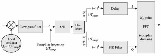
Digital I/Q block diagram is shown below

31_1184143144.jpg


as you can see, this method requires a single demodulator , but the DAC must work in twice the sampling rate

regards

Added after 2 minutes:

i must notice that the FFT block is not related to the I/Q generation , it was used for OFDM generation
 

    crenyen

    Points: 2
    Helpful Answer Positive Rating
digital iq low if

Thanks.
The web sits and picture what you posted is really helpful for me to understand.
By the way, ADI had announced AD9353 and AD9352 WiMAX tranceiver with ADI/Q interference.
Is ADI/Q concept the same as digital IQ?

**broken link removed**
 

digital communication and iq generation

Yes, the WiMAX ADI part is a ZeroIF DigitalIQ

I assume that it is a LVDS interface like there ADCs with clock and strobe. But I am not shure if it is also bidirectional.

Also the 12Bit-160MS/s is simply overkill!!! You need around 2x sample rate and about 10-11bit. So for up to 20MHz BW WiMAX it seems that ADI propose not serious numbers.

But the concept is straight because it allows to go the PHY/MAC complete in digital. I habe heard from SiliconLabs that the converter integration and digital channel filtering for DVBS is very difficult because of noise commin back to the RF frontend within the die.
 

Status
Not open for further replies.

Part and Inventory Search

Welcome to EDABoard.com

Sponsor

Back
Top