FenTrac
Full Member level 5

- Joined
- Jul 6, 2014
- Messages
- 248
- Helped
- 50
- Reputation
- 102
- Reaction score
- 54
- Trophy points
- 1,308
- Location
- West Coast
- Activity points
- 4,264
1 wire LCD interface
This project is for a simple 1 wire interface for LCD displays,
using 8 bit asynchronous communication.(8N1)
Interfaces for 2 types of displays are shown.
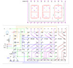
The first is for a 3 digit 7 segment LCD display.
The second for a 16x2 LCD display.
The project began with some 3 digit 7 segment LCD's found at a surplus electronics store. They were inexpensive, but require 24 pins, and phase clocking to drive them. Using 3, CD4543 7 segment LCD drivers reduced the pin count to 10. Adding
the ATtiny24/44/84 got the pin count down to 1. The ATtiny generates the backplane/phase clock, selects the digits, controls the decimal points and receives serial data at 115200 baud. To get the baud rate up to 115200 required using assembly language.
The .asm and .hex files and wiring diagram are included below:

View attachment 3digit7segment_asm.txt
View attachment 3digit7segment_hex.txt
16x2 LCD displays are used with 8 bit or 4 bit parallel, or 2 bit I2c or SPI serial interfaces,
using chips like the MCP23008. After making the 3 digit LCD interlace it seemed it would be nice to have a 1 wire interface for 16x2 displays that would be easy to use.
The .asm and .hex files and wiring diagram are included below:

View attachment 4bit16x2LCD_asm.txt
View attachment 4bit16x2LCD_hex.txt
The interfaces use an ATtiny84 (or 24 or 44) running with an 8 MHz internal clock.
ATtiny84's don't have internal UARTs, so a pin change interrupt and timer are used to make an interrupt driven serial receiver.
For the 3 digit 7 segment display, the serial data byte is encoded as below:
bits 0 - 3, are the number, 0-9, to be displayed
bits 4,5, are the right and left decimal points, 1 = on, 0 = off;
bits 7,6, are the digit the number goes to, 00 = right, 01 = center, 10 = left
For the 16x2 LCD display:
The ATtiny initializes the display on reset/power-on, so
all that needs to be done is send the data to be displayed.
Data is sent to the display at 9600 baud.
To send a command, (which is not displayed) the hexadecimal value 0x11 is sent first, followed by the
command byte.(0x11 sets RS to 0 for one following byte).
This project is for a simple 1 wire interface for LCD displays,
using 8 bit asynchronous communication.(8N1)
Interfaces for 2 types of displays are shown.
The first is for a 3 digit 7 segment LCD display.
The second for a 16x2 LCD display.
The project began with some 3 digit 7 segment LCD's found at a surplus electronics store. They were inexpensive, but require 24 pins, and phase clocking to drive them. Using 3, CD4543 7 segment LCD drivers reduced the pin count to 10. Adding
the ATtiny24/44/84 got the pin count down to 1. The ATtiny generates the backplane/phase clock, selects the digits, controls the decimal points and receives serial data at 115200 baud. To get the baud rate up to 115200 required using assembly language.
The .asm and .hex files and wiring diagram are included below:

View attachment 3digit7segment_asm.txt
View attachment 3digit7segment_hex.txt
16x2 LCD displays are used with 8 bit or 4 bit parallel, or 2 bit I2c or SPI serial interfaces,
using chips like the MCP23008. After making the 3 digit LCD interlace it seemed it would be nice to have a 1 wire interface for 16x2 displays that would be easy to use.
The .asm and .hex files and wiring diagram are included below:

View attachment 4bit16x2LCD_asm.txt
View attachment 4bit16x2LCD_hex.txt
The interfaces use an ATtiny84 (or 24 or 44) running with an 8 MHz internal clock.
ATtiny84's don't have internal UARTs, so a pin change interrupt and timer are used to make an interrupt driven serial receiver.
For the 3 digit 7 segment display, the serial data byte is encoded as below:
bits 0 - 3, are the number, 0-9, to be displayed
bits 4,5, are the right and left decimal points, 1 = on, 0 = off;
bits 7,6, are the digit the number goes to, 00 = right, 01 = center, 10 = left
For the 16x2 LCD display:
The ATtiny initializes the display on reset/power-on, so
all that needs to be done is send the data to be displayed.
Data is sent to the display at 9600 baud.
To send a command, (which is not displayed) the hexadecimal value 0x11 is sent first, followed by the
command byte.(0x11 sets RS to 0 for one following byte).