Vermes
Advanced Member level 4

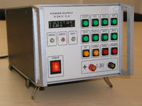
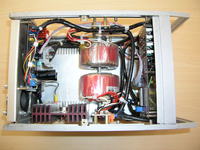
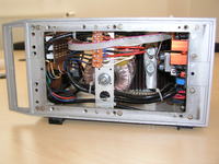
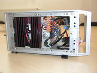
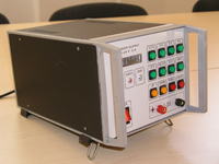
The housing was taken from Meratronik P303 power supply, the plates from AVT 5161 kit. The control board was installed on distances 40mm to the front panel. This was dictated by the desire to use the array buttons and not “default” microswitches. 3-pin connectors were soldered into the control board and the buttons are equipped with a short cable finished with the appropriate plug. Thus there is no excess of cable. The display was soldered through a header comb of 35mm height. Mechanical assembly at the appropriate distance pins. Power transistors 2N3055 in housings TO3 were used. Two transformers of high-voltage winding of 7,5V+7,5V were used. Toroids also have wound secondary winding of 14V. They are ideal as power supply for auxiliary stabilizers on AVT 5161 plate. They were hung on threaded rod mounted inside the housing. The transformers were flooded inside with resin filler.
Ventilators were installed on the outside of the rear wall, opposite the heat sink.
The front wall was made of epoxy laminate, copper-free in the power supply connectors location. The board was projected in Corel. Thanks to that, there were no problems with holes routing. The print of routing go to properly cut laminate board and was drilled. Holes for buttons were cut with Dedra foraminifera. Descriptions were printed on cardboard with ink jet, which was then covered with adhesive foil.
It is good to insert a relay between the board of power supply and the output terminals. Coil connected to one of the windings of transformers.
Tests under bad conditions indicated that the device heats up to 56 degrees Celsius.
Link to original thread – Zasilacz "mikroprocesorowy" AVT 24VDC/5A w moim wykonaniu