Continue to Site

Welcome to EDAboard.com

Welcome to our site! EDAboard.com is an international Electronics Discussion Forum focused on EDA software, circuits, schematics, books, theory, papers, asic, pld, 8051, DSP, Network, RF, Analog Design, PCB, Service Manuals... and a whole lot more! To participate you need to register. Registration is free. Click here to register now.

ИH-9 NIXIE BARGRAPH TUBE Russian language datasheet (Can anyone translate?)

Status
Not open for further replies.

schmitt trigger

Advanced Member level 5
Joined
Apr 17, 2013
Messages
2,725
Helped
859
Reputation
1,722
Reaction score
850
Trophy points
1,393
Activity points
18,445
I found this item on EBAY, which looks very intriguing.

It is essentially a bargraph Nixie.

Although the specs are in Russian, I believe that the lowest bargraph range is 140V, the highest is 250V, and that at that particular level, the current should be limited to 12 mA. See attached photos.

But of course, not able to read Russian, I may be understanding everything wrong.

I would appreciate if any Russian speaking forum member would help with the translation.
Capture 1.PNG
Capture 2.PNG
 

I used Online OCR then google translate. I should do it for my IV-1? VFD's too.


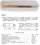
Linear indicator of a glow discharge for operation as a visual indicator of electrical signals and control measuring devices, in control systems of technological processes and other equipment.
Indication is made on the height of the glowing column through the side surface of the cylinder. The decoration is glass. Weight 15 g.
Electrode leads: 1-anode, 2 - cathode (central terminal).

Basic data:

Brightness of light >40 cd/m^2
Viewing angle >50 °
Power supply voltage >250V
The discharge voltage is <140V
Voltage maintaining the discharge <70V
Current of <12 mA
Length of luminous pillar 20-97 mm
Uncertainty error (reduced) <4%
Working hours >2000 h
===================================================================================================================
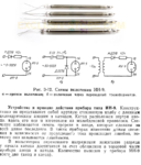
Fig. 3-12. Schematics for using ИН-9 (IN-9).
A is direct inclusion; 6 - switching on via a transformer.

The device and the principle of operation of the device type IN-9:

Structurally, it is a round glass flask with a long cylindrical anode and cathode.
The cathode is located inside the anode. Along its axis, which is made of molybdenum wire.
The glow is observed through the slots in the anode, which are made of the whole length of the anode.
In such instruments, the change in the length of the luminescence, depending on the passing current, occurs linearly, so they are called linear.

In voltmeters of alternating voltage, ignition of the discharge at the beginning of the cathode is achieved by approaching the anode and the cathode in the end part of the device.
The number of leads for the IN-9 device is only two (anode and cathode).
 
I'm not so familiar with gas tubes, so I'm not sure about some terms, but in general Google translate is almost correct, although some lines are not.

Current of <12 mA --> Indication current <12 mA

Uncertainty error (reduced) <4% --> Nonlinearity error <4%

A is direct inclusion; 6 - switching on via a transformer. --> A - direct connection scheme, B - connection via a transformer.
 
Thanks everyone for your help!

Prairedog: I had forgotten about the OCR/translate combo. My brother used it a while back to translate some information from the Korean. I had forgotten about it.

Altaero: thanks for the clarification. I am perfectly aware that Google translate has some limitations, and that many times it is required that a native speaker like yourself, to translate the language's subtleties.

If you have not played with Nixies or Dekatrons or other glow tubes, I encourage you to do so. Once that you see the soft glow of a discharge tube, you'll love them. There are many Youtube videos, but it does not do justice to their beauty.
 

Really a neat part. I've bought a lot of old Russian parts and very well made and part of the fun is figuring out the datasheet ;)
It seems this bargraph tube part is current-operated - So in all cases you need a ballast resistor to limit current under 12mA at 100% full scale.
It could be 70-140V resulting across the part. I guess it's neon inside.
 

It looks like a magic eye used on the old radios to indicate the signal strenght.
You can find it in many old radios, it works on the grid voltage, that was used to drive the AGC on AM reception.
 

It looks like a magic eye used on the old radios to indicate the signal strenght.
Different principle altogether I'm afraid.
"Magic Eye" tubes used a fluorescent paint which produced light when hit with electrons from a heated cathode. The grid voltage deflected the electron beam, creating a shadow where the electrons were prevented from reaching the paint. More negative on the grid meant more deflection and a wider shadow.

The bargraph tube works by ionizing gas along the length of one electrode. It produces red light from neon gas rather than a fluorescing target. I'm not sure how the column length is made different by voltage applied but I would guess the distance between electrodes is tapered so the narrowest part glows at lowest voltage and the 'breakdown' (ignition) voltage increased as the gap gets wider. It takes some clever design to keep a clean edge on the glow though as ionized neon tends to 'spread', lowering the breakdown voltage of neighboring gas molecules.

Brian.
 

I agree with you Brian.
There must be a very clever design and assembly trick, to actually taper the light emission as the current level increases.
 

The bargraph tube works by ionizing gas along the length of one electrode. It produces red light from neon gas rather than a fluorescing target. I'm not sure how the column length is made different by voltage applied but I would guess the distance between electrodes is tapered so the narrowest part glows at lowest voltage and the 'breakdown' (ignition) voltage increased as the gap gets wider. It takes some clever design to keep a clean edge on the glow though as ionized neon tends to 'spread', lowering the breakdown voltage of neighboring gas molecules.Brian.

Is that something similar to the LCD displays we see often on the duracel cells that show the level of charge left (it actually measures the voltage but that is a different story)?
 

Completely different!

The 'test' strip is conductive, it heats from current flowing from the battery and indicates the temperature rise. Its a kind of resistor with a tapered heat characteristic coupled with a chemical that changes polarization to allow visibility to an brightly colored background. The test button is a real electrical membrane switch.

Brian.
 

It takes some clever design to keep a clean edge on the glow though as ionized neon tends to 'spread', lowering the breakdown voltage of neighboring gas molecules

It just is a small V because the range is rather small. But I do not know how they control the striking voltage and the maintenance voltage that will give a pronounced hysteresis.
 

Status
Not open for further replies.

Similar threads

Part and Inventory Search

Welcome to EDABoard.com

Sponsor

Back
Top