Continue to Site

Welcome to EDAboard.com

Welcome to our site! EDAboard.com is an international Electronics Discussion Forum focused on EDA software, circuits, schematics, books, theory, papers, asic, pld, 8051, DSP, Network, RF, Analog Design, PCB, Service Manuals... and a whole lot more! To participate you need to register. Registration is free. Click here to register now.

[SOLVED] Amplifier, dead transistors, over-bias or oscillation ?

Status
Not open for further replies.

Mnt

Member level 5
Member level 5
Joined
Mar 20, 2016
Messages
91
Helped
2
Reputation
4
Reaction score
2
Trophy points
8
Visit site
Activity points
721
Hi there, I built this and it worked only a few seconds when the fuse in the primary blowed. Then I found out that the output transistors are dead -> 2x TESLA KD3055.

I am wondering do I need to increase R5 or this is an oscillation issue? Thanks.

123.PNG
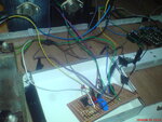
DSC05726.JPGDSC05728.JPG
 

I think the problem is caused by oscillation since the wiring is extremely messy with resistance for each long wire, capacitive coupling between all the long wires and each long wire has inductance. The high current wires are also too long and too thin.
 

Ok, ill see with an ocilloscope at the output.

"The high current wires are also too long and too thin."
They are temporary thin.
 

Did it blow with signal applied or with no signal?
To troubleshoot, first do not apply any signal at all.

Then with your DMM trace all the DC voltages on all the nodes, and check if they agree with your simulation.

Also, if you have access to a Variac, feed the amplifier at a reduced mains voltage, to see if you can spot the problem before permanent damage occurs.


Checking for spurious oscillations with a scope is also a good technique.
 
Two condition must be satisfied at switching on. Output voltage must be 0V and the output transistors collector quiscent current should be about 50mA. Bigger current will in short time because of thermal runaway cause transistors to blowup.
Circuitry must have provisions to set output voltage and quiscient current which seems are missing. Circuit is unreadable.
 

circuit is not unreadable, maybe you are confused.
there are provision to set quiscient current.
And there are not for output voltage, offset, because there are capacitor in the feedback which ensures 0V without trim pot adjustment which is better. On another hand i will implement another pcb for DC loudspeaker protection with a relay.
 

OK when you are so shure. You can use power supply and set current limit at 150mA to prevent destroying transistors while setup is done.
 

I changed the out transistors and tried again, this time with a bulb in the mains.
I crossed base and emitter wires. Collector wires are far away from the base wires.
Smth happened twice and hurted this transistor twice.
I changed it and tried again and again -> dead. :s

SDFSD.PNG
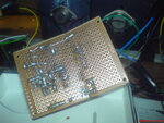
DSC05733.JPG

- - - Updated - - -

pcb bottom side DSC05740.JPG

- - - Updated - - -

I fixed it with changing the driver transistors, music played through speaker, but this was with bulb for protection, in the mains as i mentioned. Smth went wrong when I removed the bulb. Now output transistors are dead again.
This starts to creep me :S
 

A light bulb (incandescent type) is a good, proven technique to limit the current and prevent damage.

But to be effective, it has to be low wattage, 25W. Can you get one of those?
 

mine is 40W, i dont have other. i stole this one from my father :Dd
It works protecting the circuit but why this amp works only with a lamp /?

Oscillation ? I was seeing with oscilloscope but this was with the bulb.
When I removed it, the fuse blowed instantly.

Btw the sound was little distorted, is this from the bulb ?
 

Have you tried to examine the gain and phase response with the simulator for any possible instabilities?
 

I have seen a working amplifier with such type of wiring.
The only problem i know is when base and collector wires are crossing.
 
Last edited:

Your simulation of your amplifier shows plenty of gain at the radio frequency of 1MHz. If an amplifier does not have gain at high frequencies then capacitive coupling between long messy wiring and the inductance of the wiring has no effect.
 
  • Like
Reactions: Mnt

    Mnt

    Points: 2
    Helpful Answer Positive Rating
I changed C5 to 1n.
1n.PNG

- - - Updated - - -

I tried again with 1n and this time only this transistor failed -> View attachment 129088
And R1 started burning.
 

C5 cuts high input frequencies and has nothing to do with the amplifier oscillating. C1 is the frequency compensation capacitor for the amplifier that reduces amplifier gain at high frequencies where phase shift changes negative feedback into positive feedback. your messy wiring causes a lot of phase shift at high frequencies. Try increasing the 47pF of C1 to 1nF then the amplifier gain will drop above about 15kHz.
 
  • Like
Reactions: Mnt

    Mnt

    Points: 2
    Helpful Answer Positive Rating
OK, I changed the comp to 1n but i cant test because Im out of BDs.
Also I realized that one of the out transistors is dead. Not both.
Im not going to test this soon because i builded smth else in this chassis and dont have other amp to listen music. Will try someday.. Thanks audioguru.
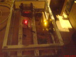
DSC05741.JPG
current.PNG
this is what im having now :)
 

Status
Not open for further replies.

Part and Inventory Search

Welcome to EDABoard.com

Sponsor

Back
Top