Raees
Junior Member level 2

- Joined
- Jun 6, 2013
- Messages
- 23
- Helped
- 0
- Reputation
- 0
- Reaction score
- 0
- Trophy points
- 1,281
- Activity points
- 1,471
Follow along with the video below to see how to install our site as a web app on your home screen.
Note: This feature may not be available in some browsers.


Hi,
your picture only shows input and putput.
For sure you need supply and other connections.
Show us your complete circuit according datasheet Fig. 21.
And the informationls like desired frequency range, supply voltage, input voltage range...
Klaus


Hi,
Did you connect all AGND with DGND?
Klaus?

This is not what I meant.yes all ground are connected at their respective locations


Hi,
Is there a reason not to connect them?
If not, then connect them and see what happens.
Klaus[/QUOTE
i have connect them. but no response..

In Figure 21, the comparator reference is used as a derived ground; the input voltage is referred to this point as well as to the op amp common mode (Pin 6 is tied to Pin 16).


Hi,
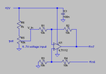
I just recognized there is a mistake in my schematic.
The two input nodes should be interchanged:
Like here:
View attachment 128162
Sorry.
Klaus


I already gave the answer:Kindly tell me why did you suggest this circuit for input. why do my circuit is not suitable?
Your amplifier circuit was not referenced to GND.to get rid of the noise your input circuit supply needs to be refereced to GND.

