Continue to Site

Welcome to EDAboard.com

Welcome to our site! EDAboard.com is an international Electronics Discussion Forum focused on EDA software, circuits, schematics, books, theory, papers, asic, pld, 8051, DSP, Network, RF, Analog Design, PCB, Service Manuals... and a whole lot more! To participate you need to register. Registration is free. Click here to register now.

[General] Table tennis scoreboard

Status
Not open for further replies.

hugo00

Member level 2
Member level 2
Joined
Jun 2, 2005
Messages
53
Helped
18
Reputation
36
Reaction score
18
Trophy points
1,288
Location
Au
Visit site
Activity points
1,687
Hello,
Anyone can point me to project of electronic TABLE TENNIS SCOREBOARD with external boards (two different colours) as well? Will appreciated.
Thank you
 

Sounds to me as though you need a two-digit counting circuit, and displays numbers on 7-segment digits.

When a player wins a point, you push the button on his side of the net. This sends a pulse, which increments the counter. The counter IC's are binary coded decimal (BCD).

You need two identical systems for two players. A microcontroller can be the central brain instead, if you wish.
 

Hello BradtheRed,
Thank you for reply, something like that.
When a player wins a point, push button on his side of the net should increase/decrease points,(4 buttons each side 2) when a player win the game again ( 4 buttons) should increase/decrease the game , (4 buttons) increase/decrease serve arrow , button should swap the site of the player and another buttons should reset the points, games, and serve, one button should turned OFF the board display.
That will be roughly all functions, maybe later the timer for the game.
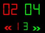
sb1.jpg big.jpg

Something likes the pic.
 

I didn't get the button functionality on each side. Explain in details what buttons you need and how they have to work. As it is weekend I might write a sample code for you.
 

I didn't get the button functionality on each side. Explain in details what buttons you need and how they have to work. As it is weekend I might write a sample code for you.

Hello pic.programmer ,
I draw approximately the buttons, but is my idea, if you think differently about the buttons please let me know so I can work something out.

control.jpg
thank you
 

I don't watch tennis and hence I don't know how tennis score board works. If you know how a tennis score board works then mention it here and I might write a C Code for you.
 

I don't watch tennis and hence I don't know how tennis score board works. If you know how a tennis score board works then mention it here and I might write a C Code for you.

Very basically:
The player points (big digits at the top, buttons POINTS + and -, - it is for adjustment mistake) when points is 11 (difference 2) than score goes up (small digit at the bottom, buttons GAME + ,-, again for adjustment mistake)arrow is for serving (arrows left right, button SEREVE 1 or2) when achieve points

- - - Updated - - -

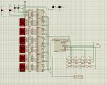
I did roughly schematic for the first part:

schematic.jpg
 
I have design this circuit and I think the buttons can be further reduced.
 

Attachments

  • Tennis Score Board.png
    Tennis Score Board.png
    47.3 KB · Views: 269

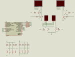
Try the attached Proteus Simulation. It is Proteus 8.2 SP2 format file. Older versions of Proteus will not open it. Internal 4 MHz Oscillator is used.
 

Attachments

  • Tennis Score Board.rar
    25.5 KB · Views: 183
  • Tennis Score Board - 1.png
    Tennis Score Board - 1.png
    33.2 KB · Views: 341
Go and check a real Score board and get info about what buttons they have and what are their functions.
 

Go and check a real Score board and get info about what buttons they have and what are their functions.

Yes I did before I posted something on this forum, not many electronics TT scoreboards exist but what I find is what I described as will.
 

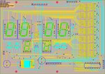
So no one have some suggestion for me, than I start to design my own SCOREBOARD, attach is the first small board for referees. Hope I get PCB soon and I did not make many mistakes on it.


1.jpg
 
Make controller board and display board different. Make it wireless. One wireless controller board should be able to drive many wireless display boards. If you need big displays then you can make big display board.
 

Hello,
I can see you newer been on Table Tennis tournament this should be NOT only for home use.

That is nice, but you looking for the users site as well, the people which will used the board they are NOT care about anything, (not pay for it, so why I should be care - damaged), another point is wireless smaller size (accidently forgot in pocket) you can NOT look and see everything what is going on. Reasonable size it will work.
I already order PCB for sample, so when I get it I can put the thing together and will see how I go.
Now I must write some software for CPU which will take some time.
 

8-O:?:

It is interesting up today 411 view(s) and only TWO people reply, what is wrong with this forum no one know or everyone just looking?

:?::?::?: :-:)-(
 

Looking at your schematic (post #7), and latest layout, it appears you decided not to multiplex the 7-segment displays. Is this the case?

Yes, if I multiplex the7-segment led (10 I/O) and multiplex the keyboard (8 I/O) 1 I/O on/off switch and at least 1 I/O for the RF transmitter I need at least 20 I/O.
But if I feed the 7 segment serially (3 I/O) keyboard (8 I/O) + on/off RF (2 I/O) it is only 13 I/O and I can use small CPU (pi16f628a / pic16f..)
Please let me know if I am wrong.
Thank you
 

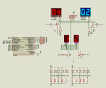
How about this circuit ? It uses PIC16F690. The keypads ares not yet coded. I will post the full code soon. It will use One-Wire ADC Keypad. The display part is working fine. It's time to code the Keypads.
 

Attachments

  • Tennis Score Board.png
    Tennis Score Board.png
    39.8 KB · Views: 340
  • Tennis Score Board.rar
    25.3 KB · Views: 144

Status
Not open for further replies.

Similar threads

Part and Inventory Search

Welcome to EDABoard.com

Sponsor

Back
Top