righteous
Full Member level 2

- Joined
- Nov 29, 2017
- Messages
- 130
- Helped
- 0
- Reputation
- 0
- Reaction score
- 0
- Trophy points
- 16
- Activity points
- 1,282
Gents,
These days I'm trying to identify my BEMF (BEMF=voltage induced in the coil by the moving magnetic field) in my BLDC system, but I can't seem to find it, maybe you can help me?
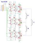
This is the circuit diagram for your kind reference

This is the scope shot of phase A
ch3 control signal for A(high side) ACTIVE LOW
ch4 control signal for A(low side) ACTIVE HIGH
ch1 and ch2 is the voltage across the coil
WHITE TRACE is ch1 - (minus) ch2

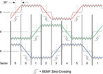
As you can see the calculated white trace resembles somewhat the theory taken from **broken link removed**

BUT... when I put ONE probe ONLY and connect it directly across the coil, the picture is totally different

So... where is my BEMF in the above scope shot?
These days I'm trying to identify my BEMF (BEMF=voltage induced in the coil by the moving magnetic field) in my BLDC system, but I can't seem to find it, maybe you can help me?
This is the circuit diagram for your kind reference

This is the scope shot of phase A
ch3 control signal for A(high side) ACTIVE LOW
ch4 control signal for A(low side) ACTIVE HIGH
ch1 and ch2 is the voltage across the coil
WHITE TRACE is ch1 - (minus) ch2

As you can see the calculated white trace resembles somewhat the theory taken from **broken link removed**

BUT... when I put ONE probe ONLY and connect it directly across the coil, the picture is totally different

So... where is my BEMF in the above scope shot?


