Continue to Site

Welcome to EDAboard.com

Welcome to our site! EDAboard.com is an international Electronics Discussion Forum focused on EDA software, circuits, schematics, books, theory, papers, asic, pld, 8051, DSP, Network, RF, Analog Design, PCB, Service Manuals... and a whole lot more! To participate you need to register. Registration is free. Click here to register now.

[SOLVED] Quadrant-1 Motor PWM: Where does the BEMF hide?

Status
Not open for further replies.

righteous

Full Member level 2
Full Member level 2
Joined
Nov 29, 2017
Messages
130
Helped
0
Reputation
0
Reaction score
0
Trophy points
16
Visit site
Activity points
1,282
Gents,

I was reading this rather informative blog from Texas Instruments called So, Which PWM Technique is Best? but it didn't quite answer my question.
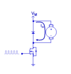
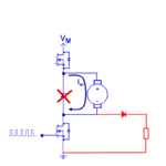
1738.Single-Quadrant-Drive.png

My assumtion is that the BEMF is looping around the diode and the motor, if I'm right in my assumption, then how to prevent the BEMF from circulating and thereby aiding coasting? Is it possible to persuade the BEMF to pick another route? I mean other than going full H-bridge and Quadrant-4?

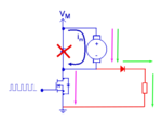
Wouldn't this be possible? The BEMF is dissipated in the resistor?
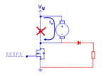
Screenshot from 2018-04-09 14-12-06.png

Regards
 
Last edited:

The problem with your proposed circuit, is that even with the Mosfet compeltely disabled, there will be still a current flow from Vm thru the motor, and then thru R and D into ground.
 

Hi,

I assume your question is regarding
* slow decay mode --> to keep current high, high torque, good RPM stability
* fast decay mode --> to reduce current. After a short circuit condition. for torque control.

Klaus
 
The problem with your proposed circuit, is that even with the Mosfet compeltely disabled, there will be still a current flow from Vm thru the motor, and then thru R and D into ground.

I understand. But then couldn't you just add a high side FET and then turn that one off?
Screenshot from 2018-04-09 14-12-06-1.png

Or increase voltage potential above V(m) after the diode with a cap or something?

- - - Updated - - -

Hi,

I assume your question is regarding
* slow decay mode --> to keep current high, high torque, good RPM stability
* fast decay mode --> to reduce current. After a short circuit condition. for torque control.

Klaus

Well, I'm actually trying to figure out by experimentation how the motor will operate without the BEMF, so I want to remove the BEMF from the equation so to say.
 

But then couldn't you just add a high side FET and then turn that one off?
No. You will burn both FETs, most likely.

Well, I'm actually trying to figure out by experimentation how the motor will operate without the BEMF, so I want to remove the BEMF from the equation so to say.
A motor will always have BEMF. You are misunderstanding something.
 

No. You will burn both FETs, most likely.

Why is that?

A motor will always have BEMF. You are misunderstanding something.

Yes most probably. I noticed that DC Motor guys use BEMF or CEMF (Counter EMF) and I can't really figure out what they mean by that. But I'm referring to the BEMF of the collapsing magnetic field of the coil in the motor that occurs when you turn the FET off, as you normally do in e.g. switching power supplies. It is this BEMF I want to take an alternative path.
 

Why is that?
When you turn OFF both FETs, your current "Im" can not flow nowhere.

It is this BEMF I want to take an alternative path.
So I was right you are misunderstanding something.

BEMF is a voltage, so it can not take an alternative path ! It will always be between the "+" and "-" terminals of the motor.
I guess that you are trying to give an alternative path for the current.. I do not understand why you do not like the 1st circuit figure in post #1.
 

When you turn OFF both FETs, your current "Im" can not flow nowhere.

But what about the body diodes? The will conduct?

So I was right you are misunderstanding something.

Yes absolutely, there is a lot of things I do not understand and that no one can explain to me. Actually my "unknowns" are a multitude larger than my "knowns".

BEMF is a voltage, so it can not take an alternative path ! It will always be between the "+" and "-" terminals of the motor. I guess that you are trying to give an alternative path for the current..

Yes probably that is what I'm trying to achieve. Also I have never understood the concept of current without voltage.

I do not understand why you do not like the 1st circuit figure in post #1

Two things, I like to experiment, and secondly because I want it to do something like this:

boost-converter-basic-cct.gif

In my mind the motor is the same as the coil in above schematic, and here current and voltage is finding it's way to the other side of the diode, so why can't it do the same in figure #2 in post #1?
 

Hi,

There are several misunderstandings.
See this picture:
magenta: MOSFET is LOW ohmic
green: MOSFET is high ohmic
InducCurr.PNG
* Current through L is always in the same direction
* body diode of MOSFET is never active

**********
BackEMF of a motor is something different than BackEMF of an inductance.
Refer to Wikipedia:
https://en.wikipedia.org/wiki/Counter-electromotive_force
Where it says:
The term back electromotive force is also commonly used to refer to the voltage that occurs in electric motors where there is relative motion between the armature and the magnetic field produced by the motor's field coils, thus also acting as a generator while running as a motor. This effect is not due to the motor's inductance but a separate phenomenon.

Klaus
 

Hi,

There are several misunderstandings.
See this picture:
magenta: MOSFET is LOW ohmic
green: MOSFET is high ohmic
View attachment 145911
* Current through L is always in the same direction
* body diode of MOSFET is never active

Yes, but how is that different from this?
Screenshot from 2018-04-09 18-58-40.png

Then slap a cap on after the diode to keep V(r)>V(m) ?

BackEMF of a motor is something different than BackEMF of an inductance.

Yes, that's it, BackEMF is not BackEMF some times. So when the DC motor guys says BackEMF, they actually mean the current and voltage that is exited in the coil by the rotor?

- - - Updated - - -

No body diode will conduct in figure of post #4.

Ok, that was actually the figure I was referring to.

Yes it can. Re-read post #2.

Yes, and then Herrn. Schmitt said "there will be still a current flow from Vm thru the motor, and then thru R and D into ground." and then I said "increase voltage potential above V(m) after the diode with a cap or something?"

Is that the way to go?
 

Hi,

Yes, but how is that different from this?
1st difference: motor <--> inductance. It´s not the same. The generated voltage is opposite.

2st differnce - or better say "problem". The motor never is OFF. Either the current runs through the MOSFET or it runs through the d-R combination.
If you make R high impedance it won´t kill voltage peaks. If you make it low impedance the motor won´t stop.
Can you find a good compromise value?

3rd - where is the benefit?

**
At a real motor you will see a negative high voltage peak caused by stray inductance, then it becomes a positive voltage that is proportional to RPM.
You need to avoid/suppress the negative voltage peak, otherwise it may kill the semiconductors.

Klaus
 

1st difference: motor <--> inductance. It´s not the same. The generated voltage is opposite.

I will take your word for that the voltage is opposite, but how? (EDIT: ahhh you mean the generated voltage of the coil excitement?, yes that I was aware of)

And what do you mean by "motor <--> inductance. It´s not the same."? A motor has a coil, a coil has inductance? The only slight difference I can see is that from time to time some magnets are zipping past the coil while it is on.

2st differnce - or better say "problem". The motor never is OFF. Either the current runs through the MOSFET or it runs through the d-R combination.
If you make R high impedance it won´t kill voltage peaks. If you make it low impedance the motor won´t stop.
Can you find a good compromise value?

I proposed to put something after the diode to keep V(r) above V(m) e.g. a cap or a battery, then the diode is reverse biased and current can't run through the D-R combo, so the motor will actually be off during (inductive) BEMF?

3rd - where is the benefit?

I don't know yet, but that's what research is all about, maybe there is none, maybe there is all, only a bit of experimentation can tell.

At a real motor you will see a negative high voltage peak caused by stray inductance, then it becomes a positive voltage that is proportional to RPM.
You need to avoid/suppress the negative voltage peak, otherwise it may kill the semiconductors.

Where does stray inductance occur and come from in a motor?
 
Last edited:

Yes, and then Herrn. Schmitt said "there will be still a current flow from Vm thru the motor, and then thru R and D into ground." and then I said "increase voltage potential above V(m) after the diode with a cap or something?"

Is that the way to go?
Yes you could.

By the way, in post #1, what do you mean by "aiding coasting" ?
 
Last edited:

Hi,

And what do you mean by "motor <--> inductance. It´s not the same."? A motor has a coil, a coil has inductance? The only slight difference I can see is that from time to time some magnets are zipping past the coil while it is on.
I should have written: "motor_backEMF is not the same as inductor_backEMF"

I proposed to put something after the diode to keep V(r) above V(m) e.g. a cap or a battery, then the diode is reverse biased and current can't run through the D-R combo, so the motor will actually be off during (inductive) BEMF?
Ok. "Something" is a bit vague to discuss about.
" to keep V(r) above V(m)" ..... others use a zener to get this

The result is, that via V(r) some power needs to be dissipated...dissipated means that it is firmed into heat without beeing abke to be used as electrical energy. A waste of energy, somehow.

Where does stray inductance occur and come from in a motor?
Stray inductance is everywhere. Every piece of wire causes stray inductance...and for sure the wiring inside a motor, too.

Klaus
 

I see the terms counter or back e.m.f. rarely used in the basic electrical drive engineering text books. The usual technical term is armature winding e.m.f. or just e.m.f., see e.g. Gieras, Wing Permanent Magnet Motor Technology - Design and Applications.

They are more often found in popular science explanations of motor operation.

Post #1 is an example how using the same term for two contrary effects can cause confusion. The diode circuit is the dedicated path for armature inductance fly-back voltage, motor e.m.f. has opposite polarity so that the diode blocks any related current flow. Only reverse spinning the motor opens the diode.

The OP claimed
But I'm referring to the BEMF of the collapsing magnetic field of the coil in the motor that occurs when you turn the FET off, as you normally do in e.g. switching power supplies. It is this BEMF I want to take an alternative path.
But why? The fly-back diode is there to protect the switch transistor and also to recirculate the energy stored in armature inductance instead of dissipating it, particularly useful in PWM operation.
 
  • Like
Reactions: CataM

    CataM

    Points: 2
    Helpful Answer Positive Rating
Yes you could.

And so I did, I soldered the darn thing up, and it sucks somehow e.g. the circuit is drawing 200mA but I can only recover say 10mA before the voltage drops below V(m), I was really expecting something better, I would be happier with 50% and even happier with 90%. This way the motor can put in a high efficiency state while still spinning, albeit with lower torque but still keeping RPM's, and that is what I want.

By the way, in post #1, what do you mean by "aiding coasting" ?

Based on the claims in the TI blog (part 3, third paragraph):

"whenever Q4 turns off, the inductive flyback current is captured in the top half of the H-Bridge until it is extinguished."

I'm assuming the inductive flyback current is aiding forward motion and coasting.

- - - Updated - - -

The usual technical term is armature winding e.m.f. or just e.m.f.

That would also be the term I would use in this context.

But why? The fly-back diode is there to protect the switch transistor and also to recirculate the energy stored in armature inductance instead of dissipating it, particularly useful in PWM operation.

Because this way the motor can put in a high efficiency state while still spinning, albeit with lower torque but still keeping RPM's, and that is what I want.

I surfed the interwebs and found this example of a high efficiency PWM'ed brushless **broken link removed** , it's efficiency is just below 100%, so I figured I could achieve something in the high 90% with a standard BLDC, or at least that is what I hope.

- - - Updated - - -

Ok. "Something" is a bit vague to discuss about.
" to keep V(r) above V(m)" ..... others use a zener to get this

As mentioned, I soldered the darn thing up, and it sucks somehow e.g. the circuit is drawing 200mA but I can only recover say 10mA before the voltage drops below V(m), I was really expecting something better. So my "feeling" is that I'm not recovering flyback current as much as is possible.
 

The original fly-back diode gives high efficiency in single quadrant PWM control. Only a synchronous switch gives slightly better efficiency by removing the diode voltage drop. The imagined "alternative" path solutions are no way better.
 

The original fly-back diode gives high efficiency in single quadrant PWM control. Only a synchronous switch gives slightly better efficiency by removing the diode voltage drop. The imagined "alternative" path solutions are no way better.

OK, then I'll do as the textbooks suggests, that should give the desired effect:

Texas Instruments said:
When Q3 is now switched OFF, and Q4 is switched ON, the inductor now looks for an alternate path to keep its current flowing in the same direction. And what is that path? It turns out that the new path of least resistance is to flow in the reverse direction through Q1, back through the DC power supply AS NEGATIVE CURRENT, and then return in the reverse direction through Q4. If your DC bus has positive voltage and negative current, then that means that it has negative power during that instance. This negative bus current will charge up the bus capacitor to a higher voltage until the inductive flyback is quenched, or the next switching state is applied

- - - Updated - - -

This was actually what I wanted "Regenerative Braking" - I just didn't know it existed and therefore I could not express it in the right terms:

Regenerative-Breaking-of-dc-Motor.jpg

https://www.circuitstoday.com/choppers-an-introduction
 

O.K. regenerative breaking needs at least a second transistor switch and diode (unidirectional, two quadrant operation). Or a H-bridge for bidirectional, 4 quadrant.
 

Status
Not open for further replies.

Part and Inventory Search

Welcome to EDABoard.com

Sponsor

Back
Top