Continue to Site

Welcome to EDAboard.com

Welcome to our site! EDAboard.com is an international Electronics Discussion Forum focused on EDA software, circuits, schematics, books, theory, papers, asic, pld, 8051, DSP, Network, RF, Analog Design, PCB, Service Manuals... and a whole lot more! To participate you need to register. Registration is free. Click here to register now.

Circuit problem. Not getting 5 Volt on 7805 output

Status
Not open for further replies.

aqua_life

Newbie level 6
Newbie level 6
Joined
Mar 23, 2013
Messages
14
Helped
0
Reputation
0
Reaction score
0
Trophy points
1,281
Visit site
Activity points
1,468
Hello,
I am developing a circuit to have power and communication on the same wire.
So, I thought about a digital signal that would vary from 5 Volt to 8 Volt.
This way I am able to send signals to another processor and at the same time power that processor.
All working good with the second processor.
Here you can see the type of signal I am generating with a PIC12F processor and two voltage regulators (7808 and 7805).
aaaaaaaa1.jpg

Here you can see the schematic I have now to produce this signal.
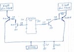
aaaaaaaa2.jpg

As you can see on the schematic the processor 12F from microchip will turn ON or OFF the outputs to have 5V or 8V at the final Signal. Off course the processor never turns ON both outputs at the same time. Everything is working correctly and the signal is OK.
However when the processor is generating the signal the 7805 output is not 5 Volt as it should. The output is around 5,7 Volts. I have been thinking about this problem and I think this happens because when processor turns OFF 8 Volt and turn ON 5 Volt there is some current flowing to 7805.
Easiest solution was to place a diode on 7805 output. I tried this and then output is ok, at 5 Volt.
But this is not a good solution for me because the diode will take 1 Volt on the 7805 output so the signal will not be 5V - 8V. It would be 4V - 8V and this is not good for me.

Any other solution that might know ?

Many thanks for your help.
 

Hi,

First: Congratulations, you are of a of a view that are able to give good informations in the first post.
Even the hand drawn pictures show all information like timing, voltage..

***
To the problem:

A diode on the right side could simplify things. For lower voltage drop you may use a schottky diode. A drop of 0.3V should be no problem. You may compensate this by adding the same diode in the GND line of the voltage regulator. Add a ceramics 100nF in parallel to this diode. Then the VR output will be slightly higher than 5V. If this us the supply for the microcontroller: check datasheet if the UC can stand this.

On the other hand you may continously switch ON the right side, there will be no significant reverse current flow.

Your circuit looks correct. The VR output is specified with a "minimum load" maybe you need to add a resistor as extra load to the VR output.
Also the VR needs input capacitor and output capacitor. Did you install them close to the VR?

If the problem still exists then please upload a photo of your circuit.

The load RC creates a slow decay with tau of about 1ms. Risetime will be faster.

Klaus
 
You say 5.7V at the 7805 output? Required regulator bypass capacitors fitted?

A solution with lower part count would be a single programmable regulator (e.g. LM317) with switched feedback network.
 
KlausST many thanks for your help.
I really appreciate it.
I have not thought about the schottky diode solution. It seems a good solution.
I will try it during next days and report here.

Again, many thanks for your help.
I love programming PIC´s and make some electronic projects, which is not my job.
So, it is very good to have a place like this forum to share ideas and find solutions for our "electronic problems".
 

I see no reason for the 5V to be 5.7V unless it's oscillating from lack of filter capacitors at its input and output pins.

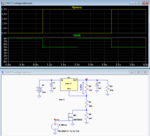
Below is the LTspice simulation of a circuit using one LM317 as FvM suggested.
Is uses a small MOSFET to bypass R4 which switches the output from 8V to 5V.

An NPN BJT could also be used as a switch, but it has a slighter higher output ON voltage.

Capture.PNG
 
FvM and crutschow many thanks for your help.
I have been reading LM317 datasheet and it also seems a very good solution, as you suggest.
I will buy all components needed during this week and try the different solutions proposed by you.

Also another question... I would like to protect the the signal wire than varies from 5 to 8 Volts against short circuit to ground.
I have been looking for solutions on the web and I think I found an easy an reliable solution.
I will use a Zener diode from the LM317 output to its input.
In my circuit Vin is 12 Volt. LM317 lowest voltage output is 5V, so maximum voltage break is 7 Volt.
I will use a 11 Volt Zener diode with load current 500 mA.
So, if the signal wire has a short circuit to ground, voltage difference between LM317 input and output is 12 Volt. This way Zener diode will conduct and will force a fuse to blow on the input of my circuit. I will use a 400 mA fuse.

What do you think of this idea ?

Thanks for your help.
 

I'm not sure how a Zener diode from output to input will help. It will conduct like any normal diode in one direction and only limit the in/out difference in the other.
Did you mean to connect it from output to ground?

For your voltage modulation, I would do it in an even simpler way than Crutschow demonstrates. Just add a potential divider from the PIC output to ground such that a '1' on the output pin raises the junction to 3V, a'0' will always produce 0V at the junction. Then lift the ADJ pin of the LM317 to 3.5V (a Zener or resistor) above that and it's output pin will switch 5V to 8V. The other method is to use a 'normal' resistor divider to set the LM317 to produce 8V then connect the ADJ pin through a resistor to the PIC output. Leave the PIC output pin driven low and use the TRIS bit so it either pulls low or doesn't pull at all. Effectively, the TRIS bit adds or removes a parallel resistor at the bottom of the divider pair.

Brian.
 

aqua_life: Also another question... I would like to protect the the signal wire than varies from 5 to 8 Volts against short circuit to ground.
...............
I will use a Zener diode from the LM317 output to its input.

The LM317 has a built-in current limit and short circuit protection, so I don't see why you want to add the zener (?).

betwixt: The other method is to use a 'normal' resistor divider to set the LM317 to produce 8V then connect the ADJ pin through a resistor to the PIC output.
That means the PIC output will need to withstand 6.75V when off and I don't think it can do that.
 
Last edited:
Thanks for your help.
I will try your various solutions during this week on the real circuit and see which one is the best for me.
In your opinion how can I protect this circuit from short circuit to ground ?
If I have the LM317 producing 5V or 8V, then this wire has a short circuit to ground, the voltage regulator will control and limit the output current and it will not allow a fuse to blow on the input of the circuit (I have tested this).
So, in a case of a short circuit how could I force the circuit to blow a fuse ?

Many thanks for your help.
 

So, in a case of a short circuit how could I force the circuit to blow a fuse ?
Normally a fuse is to protect the circuit from damage, but if the LM317 is limiting the current, why do you want to fuse to blow?
What are you trying to protect?

If you need it to blow, then use a 1A fuse, as the LM317 typically limits as some over an amp.
 

My circuit only needs some mili Amps.
So, I will be using a LM317LZ with 100mA max output.
I tested now on my bench with a 12 Volt voltage supply, if I create a short circuit to the ground on the LM317 output it will drain 170mA for some time. I waited more or less 30 seconds until I saw some smoke coming out of the LM317. I am just testing... Also, I had a 150mA fuse connected and it didn´t blow.
What could I do to force the circuit to blow a fuse ?
Thanks for your help
 

Hi,

Read the fuse datasheet. Usually the specified current is the "hold" current.
The trip current is (much) higher and it takes a lot of time.

Use a 50mA fuse.

Klaus
 

That means the PIC output will need to withstand 6.75V when off and I don't think it can do that.

Only if the pin connects directly to ADJ.

I suggest doing it this way:
LM317LZ
+12V to it's input
240 Ohms from OUT to ADJ
Two resistors in series between ADJ an ground, 620 Ohms and 680 Ohms with latter at ground side.
PIC output pin driven low connects to junction of the two resistors.

With TRIS bit set to 1 (input), the voltage will be 8V
With TRIS bit set to 0 (output), the voltage will be 5V
The PIC pin has ~0V on it when an output and ~3.5V on it when an input.

Brian.
 
The PIC pin has ~0V on it when an output and ~3.5V on it when an input.
How does ≈3.5V on the output translate to an exact 3V change at the resistor junction?
The micro will try to drive that point above 3V for a logic high.

That's the reason I added the MOSFET buffer, to get a precise switch between 0V and open at that junction.
 
Last edited:

We are both right!

The TRIS bit I referred to decides whether the PIC pin is an input or output (direction control bit). When driven low the output latch is taken to ~ground before the direction control circuits. Therefore, changing port direction either grounds the pin (output) or lets it float (input). The lower MOSFET in the PIC output driver essentially does what your external MOSFET does without any external active device being needed. It shorts out the lower resistor in the two-resistor chain from ADJ to ground but never drives a voltage into that point.

Brian.
 

Hi betwixt and crutschow

I also think that both solutions are correct. Anyway I have ordered some missing parts to try the various solutions you presented to me. I am very thankful for that.
I will receive the parts tomorrow, I will test the solutions and analyze with the oscilloscope.

The solution to use TRIS bit of that Pin seems a good solution and I totally understood the solution presented here.

Many thanks again for all your help and support.
 

...........

The TRIS bit I referred to decides whether the PIC pin is an input or output (direction control bit). When driven low the output latch is taken to ~ground before the direction control circuits. Therefore, changing port direction either grounds the pin (output) or lets it float (input). The lower MOSFET in the PIC output driver essentially does what your external MOSFET does without any external active device being needed. It shorts out the lower resistor in the two-resistor chain from ADJ to ground but never drives a voltage into that point......
I wasn't aware of that behavior for the processor, so that connection certainly does make sense now, without requiring a transistor.

Thanks for the enlightenment. :smile:
 

Status
Not open for further replies.

Part and Inventory Search

Welcome to EDABoard.com

Sponsor

Back
Top