Continue to Site

Welcome to EDAboard.com

Welcome to our site! EDAboard.com is an international Electronics Discussion Forum focused on EDA software, circuits, schematics, books, theory, papers, asic, pld, 8051, DSP, Network, RF, Analog Design, PCB, Service Manuals... and a whole lot more! To participate you need to register. Registration is free. Click here to register now.

DC to AC converter 12V to +/-175V (40W)

Status
Not open for further replies.

artmaster547

Newbie level 4
Newbie level 4
Joined
Feb 20, 2018
Messages
6
Helped
0
Reputation
0
Reaction score
0
Trophy points
1
Visit site
Activity points
54
Hi All
I am currently trying to simualte/design a power converter that takes in 12V and outputs +175V and -175V AC sinusoidal output (delivering a maximum power to the load of ~40W a little less than this) Can anyone suggest a good topology that I should use for this any recommendations are warmly welcome I just need a starting point to work from. The output AC waveform will also need the ability to change frequency.

Kind Regards

Art
 

...more specifically, what frequency range?
As AC cannot be defined as + or -, do you refer to 175V peak to peak or RMS?

Brian.

Sorry frequency wise I want a range of 1kHz to 40kHz and it's a peak voltage of 175 so 350V peak to peak
 

Ive never known how to make one, or the mathematics behind it all, but I would place a crystal oscillator at your desired frequency (1kHz for example). If you want a wideband signal between 1kHz and 40kHz you might need to build something more complex than just using a crystal oscillator and you might need to test it on a spectrum analyzer, to make sure you have the correct sprectrum you need. After you get your desired frequency, feed your output from the oscillator into a class B amplifier then from a class B to a transformer that will step up your voltage to 350V peak to peak. If there isn't enough voltage at the output, you could cascade another class B (dont cascade over 3 class B amplifiers though, or your circuit will become unstable). This circuit may be the worst for energy efficiency though, but I would give it a try till you finally got something you need! ;)... you could even just use a class C amplifier
 

It's doable but 350V p-p sine wave over a 40:1 frequency range isn't simple. The frequency is too high to easily use a PWM based design and the variable frequency would make filters converting square waves to sine and transformers far too inefficient. Others may have their own ideas but as the power is relatively low, I'm thinking the best approach would be:

if the output can float (not connected to the DC input)
1. convert 12V to 175V DC
2. use a linear bridge amplifier with the output taken across the bridge arms.

if the output has to share a common connection with the input
1. convert 12V DC to +175V DC and -175V DC
2. use a linear class A or AB amplifier to produce the output referenced to 0V.

Brian.
 

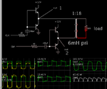
Here is a topology which is simple to put together and operate. The step-up transformer is powered by an H-bridge. It needs to handle 40 watts. It's possible to design one transformer to perform at one frequency, but the same transformer may not provide what you want over a large ratio of low-high frequencies (1:40).

power invert H-bri 12V to 120VAC 40W sine-like.png

The H-bridge is driven by alternating DC pulses. By adding a capacitor at the bias, you get 'sine-like' output waveform. However the transistors are partially On sometimes, which might result in high temperatures.
It might be possible to improve on this by experimenting with capacitors (or inductors) at different positions around the transformer.
 

By far the easiest - and possibly best way - here is to make a 12V to 200V step up converter, say push pull on the input driving side, for +/- 100V out. Then use 2 x class AB power amplifiers, rated for the +/- 100V supplies in a bridge configuration, i.e the load sits between the two amp outputs.

This will give you your 175V pk (with a little head room (25V) for the amps) sine wave at any frequency up to 40kHz (class AB amps at this freq should be relatively easy to find),

and you can drive it from a sig gen to get whatever you desire at the output.

also not too hard to design a transformer on the output if you want a fully isolated o/p ...

to make the amp part easier you can buy high volt op-amps (element 14 etc) and use these to drive an external emitter follower to give you all the power you require, at reasonably low THD.

Good luck.

- - - Updated - - -

also: page 8 AN-272 Op Amp Booster Designs SNOA600B–September 1981–Revised April 2013

circuit on page 8 allows for +/- 120V rails, so +/- 175 easily in bridge ...

- - - Updated - - -

Also: **broken link removed**

- - - Updated - - -

PAD135 200V 5A 40W Compact High Voltage Op Amp

- - - Updated - - -

and: **broken link removed**

- - - Updated - - -

and: www.edn.com/design/analog/4329148/High-voltage-amplifier-uses-simplified-circuit

download the pdf to see a very useful circuit for high voltage analog power amplifier...
 

Status
Not open for further replies.

Similar threads

Part and Inventory Search

Welcome to EDABoard.com

Sponsor

Back
Top