Continue to Site

Welcome to EDAboard.com

Welcome to our site! EDAboard.com is an international Electronics Discussion Forum focused on EDA software, circuits, schematics, books, theory, papers, asic, pld, 8051, DSP, Network, RF, Analog Design, PCB, Service Manuals... and a whole lot more! To participate you need to register. Registration is free. Click here to register now.

Hartley VCO for radio frequencies - additional products in spectrum

Status
Not open for further replies.

Eres_89

Member level 1
Member level 1
Joined
Jul 11, 2012
Messages
34
Helped
0
Reputation
0
Reaction score
0
Trophy points
1,286
Visit site
Activity points
1,651
Hi All,

Some time ago, I designed simple hartley tunable oscillator working in range 21-23 GHz band (like this presented in attachment - diode is working as a tuned capacitance in resonance circuit). How big was my surprise when during measurements I observed additional products in frequency spectrum. It's look like effect of mixing two signals ! (like in modulation process). Now I'm wondering where is cause of such behaviour and I don't have any practical idea what is going on... There are no other measured signals in band from 1Hz to 30GHz so it's look like circuit issue.

Bellow I attach measured spectrum with frequencies marked.
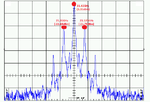
Bez tytułu.png

I'll be really appreciate for any suggestion where I should search for answer.

Regards,
E.

Bez tytułu2.png
 

You didn't degenerate the source of the FET. Probably it operates in the triode/linear region. Thus the output voltage is non-linear function of the input feedback voltage at the gate, and non-linear distortion causes mixing products.
By the way, how do you control the drain current without degeneration? I think in your topology it changes a lot with temperature, parasitics and can be high.
 

It may also be coming from dirty tuning voltage.( a switched mode power supply ?? )
 

frankrose,
in first steps of designing I tried to make some feedback by using inductor/resistor in source but according to awr/pspice simulations - oscillations were not possible, so I use presented circuit. In linear region ? Not in saturation ? Hmmm... dren current can be controlled only from external power supply, so I'm doing this as that.

BigBoss,
Yes, I'm using twi Switched Mode PSs (for VCC and VREF) and there could be also a problem... I'll check it tomorrow.

Thanks for suggestions !
 

Don't worry about the mode of operating because if an oscillator oscillates it's sure that it's working in rail-to-rail mode.So, triode or linear mode is not possible..
 

The output power is 3.35dBm. With 50Ohm analyser impedance it means 0.46V oscillation amplitude. On the other side of the C1 the voltage can be higher, but I don't know the device values, quality factor. The supply should be much higher than 0.46V. So I wouldn't be sure that the oscillation is rail-to-rail, especially if the FET operates as a triode. Oscillation max. amplitude is determined by the saturation level of the transistor, not just by the supply.
 

The output power is 3.35dBm. With 50Ohm analyser impedance it means 0.46V oscillation amplitude. On the other side of the C1 the voltage can be higher, but I don't know the device values, quality factor. The supply should be much higher than 0.46V. So I wouldn't be sure that the oscillation is rail-to-rail, especially if the FET operates as a triode. Oscillation max. amplitude is determined by the saturation level of the transistor, not just by the supply.
It's coming from the feedback definition buddy..
If an oscillator works as wanted,the poles are on the imaginary axis and this ensure the oscillator amplitude to reach VDD.It have to be otherwise the oscillation amplitudes
are damped.
 

You are talking about the steady state of the poles, fine, but it isn't coming from that if the amplitude reaches the VDD it will shifts the poles from the right half-plane to the imaginary axis.
If a FET device leaves its normal active region, the transconductance decreases. At this topology it can happen that the FET is not in the saturation region from default, and the gain is depending on the drain voltage (triode behavior). If the drain voltage decreases the operating transconductance will decrease and the loop gain too. If the loop gain reaches 1 the poles will be at the imaginary axis, amplitude won't increase further. And this limits amplitude buddy.
 

Is the reference level set on your spectrum high enough (let me say at least 10 dBm), not to have intermodulation of the instrument itself ?
 

I didn't see the bias condition of the FET.If the schematic is as shown above, the FET is zero biased so it will work at a kind of B-Class ( or C-Class )-The coils make the bias voltage short circuit.
This does not guarantee the oscillation and I think a small bias voltage should be applied because FET seems really working at triode/subtreshold region.
 

Nope. If it is an enhacement MOS it wouldn't oscillate, and if it is a depletion MOS it should have worked as a JFET. It have to be an N-JFET by its symbol. From default JFET has got an open conductive channel, it hasn't got a threshold voltage, JFET's have pinch-off voltage, and JFET doesn't have subthreshold region because there isn't threshold. So it is not a B or C class amplifier.
 
Last edited:

Hi,

sorry for late response. Well, today I changed transistor to pHEMT and problem still occurs. Furthermore, I observed that those additional products in spectrum occurs ONLY when PROBE IS TOUCHING the VREF PAD (in case when this probe is disconnected from VCO I have clear, fixed signal).

This is not problem of measuring equipment (I check how VCO is working when additional capacitors are used on the output of power supply, analyser is also calibrated and configured properly). I've made tests when probe is connected to supply and without it - effect is the same, so something is wrong with resonance circuit ?
 

Hi,

sorry for late response. Well, today I changed transistor to pHEMT and problem still occurs. Furthermore, I observed that those additional products in spectrum occurs ONLY when PROBE IS TOUCHING the VREF PAD (in case when this probe is disconnected from VCO I have clear, fixed signal).
OK, you found the source of the problem.This is simply a FM coming from measurement equipment(s). You may use a decoupling capacitor @ VREF, an additional LC(RC) filter may be used,A Ferrite Bead
can be a solution ( my preference ) or similar Hum&Noise suppression element will help you.
-What is the resistance (R2) value ??
-What type of pHEMT do you use ? Depletion or Enhancement ??
 

R2 is equal to 1.5k and used pHEMT is normally open. I tried use LC filters, and single capacitors as you suggest but still the same behaviour can be observed. Furthermore, I check that also when I'm touching pad with probes with different lengths (which are not connected to the power supply !), those products can be noticed in the spectrum.
 

R2 is equal to 1.5k and used pHEMT is normally open. I tried use LC filters, and single capacitors as you suggest but still the same behaviour can be observed. Furthermore, I check that also when I'm touching pad with probes with different lengths (which are not connected to the power supply !), those products can be noticed in the spectrum.

If the FET is normally open ( Enhanced Mode ) how your oscillator works ?? Because VGS=0V ??Right ?
 

What kind of probe do you have? Shielded coax cable?
Did you try to pull down the other side of the probe with capacitive and/or resistive load(s)?
When you put a capacitor on the vref the shielded cable had the same ground point as in your circuit that capacitor?
 

BigBoss,
My wrong - of course you have right. I just quickly compare in mind HEMT to FET.

frankrose,
I used simple "needle" probe which you can use to measuring ICs (pads are quite small) with shielded coax. I connected capacitors as closer as possible to the pad. I also try with 1k resistor as you wrote. Strange is fact, that distortion are visible only when I touch Vref pad... example: I touch it only bu using simple small screwdriver, thin wire, needle, tweezers (all without connection to power supply! ) and modulation just occurs...
 

Ok, I think if a good capacitor on the vref pin doesn't filter out the added signal from the screwdriver there is a ground loop in your circuit. You can try to put the grounded pin of your capacitor to other ground points, it should have got some effect on the amplitude of the modulation products.
 

Status
Not open for further replies.

Similar threads

Part and Inventory Search

Welcome to EDABoard.com

Sponsor

Back
Top