Continue to Site

Welcome to EDAboard.com

Welcome to our site! EDAboard.com is an international Electronics Discussion Forum focused on EDA software, circuits, schematics, books, theory, papers, asic, pld, 8051, DSP, Network, RF, Analog Design, PCB, Service Manuals... and a whole lot more! To participate you need to register. Registration is free. Click here to register now.

MCU does not boot on power up, only starts when reset button is pressed

Status
Not open for further replies.

ogulcan123

Member level 5
Member level 5
Joined
Apr 23, 2011
Messages
81
Helped
0
Reputation
0
Reaction score
0
Trophy points
1,286
Location
Istanbul, Turkey
Visit site
Activity points
2,024
MCU does not boot on power up, only boots when reset button is pressed (STM32F407VG)

Hi all,

I have a new design which is actually the second version, and this problem was not exist in the older version.

I'm using an STM32F407GVT6(datasheet) MCU with most of the peripherals that can be used including SPI, I2C, RS232, USART ect.

The problem is when I plug the circuit, I does not boot automatically, yet when I press the reset button, it boots.

I checked all the voltage levels, they are fine. I pulled down BOOT0 pin and pulled up BOOT1 (although BOOT1 is don't care when BOOT0 is 0).

The main difference between my previous version and this version is the power stage, but I'm not sure if such a problem can occur due to a mistake in the power stage.

If anyone can give me any clue of why such a problem can be occured, I can focus on it and solve the problem.

I can give more details if needed, any help is appreciated.

Thanks,
Ogulcan
 
Last edited:

Sounds like a power up sequencing or slew problem.
Does your power source produce more than one voltage and if so, do the supplies rise in the same order as before?
Is the rise time different? A faster rise time may not allow peripherals to be ready before the MCU uses them, a slower rise may allow reset to release before the MCU is ready.

If you haver a delay network on RST/BOOT0 it may need to be longer but we need to see the schematic to advise on that.

Brian.
 

Re: MCU does not boot on power up, only boots when reset button is pressed (STM32F407

What change was done in the power stage in new version ?
 

Re: MCU does not boot on power up, only boots when reset button is pressed (STM32F407

Two likely reason:

1. Reset applied too early;
2. Reset voltage changes slowly.

Both can be related to the power stage: too large filter capacitors can worsen the case.
 

Re: MCU does not boot on power up, only boots when reset button is pressed (STM32F407

Thank you for your replies.

Does your power source produce more than one voltage and if so, do the supplies rise in the same order as before?
My power stage produces 3 voltages which are 3.3V, 3.8V and 5V, but I'm not using 3.8V yet, I'll use it later for GSM. You can check it out below.
I don't know the raising rate of the voltages but the MCU does not need 5V to be operated, I've actually made the MCU work without 5V.


What change was done in the power stage in new version ?
In fact, everything has changed except for the voltages. You can check it out. I've really upgraded my power design to endure in even truck environment.


Two likely reason:

1. Reset applied too early;
2. Reset voltage changes slowly.

Both can be related to the power stage: too large filter capacitors can worsen the case.
In this power design, I've actually used some large filter capacitors which is cumulated as 702uF at my 3.3V net.


Until now, I've tried these, and I still have the same problem:
  • removed the TVS diode.
  • changed BOOT0 and BOOT1 values as well as their pull up and pull down resistors.
  • did some changes in the initialization code.
  • removed the 5V inductor to disconnect 5V to see if some defect affects the MCU.


Here is my power stage:
Power_Stage.JPG

Thanks,
Ogulcan
 

Great - thank you.

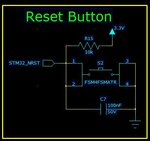
Almost certainly what is happening is the 3.3V supply to the MCU is rising slower than it used to. In order for the MCU to reset properly, the RST pin has to be held low until the 3.3V has stabilized and the clock has had time to start and perform some internal actions to get the MCU ready to run. The delay between power being applied and the reset being released is created by the time constant of R15 and C7. The voltage across C7 has to stay below the reset pin threshold for a while after the 3.3V is present. If the supply rises slowly, C7 charges up at the same time as the 3.3V line rises so the delay is reduced or not there at all.

You can try fixing it by increasing the value of C7 to say 10uF so the time constant is 100 times slower. A better solution is to use a dedicated reset IC that monitors the 3.3V then waits a few mS before producing the reset signal.

If you increase the value of C7 you should also make two other changes to ensure safety:
1. add a resistor of around 100 Ohms in series with the reset switch to prevent sparking as C7 is discharged through it.
2. add a small Schottky diode (BAT85 or similar) across R15 with it's cathode to the 3.3V line. This will ensure that if the 3.3V turns off quickly, the remaining charge on C7 goes back to supply instead of discharging into the MCU.

Brian.

Thanks Brian. However, the problem is not the reset button. My reset button works perfectly. The problem is that the MCU does not boot when I directly plug the power connector.
 

the problem is not the reset button. My reset button works perfectly. The problem is that the MCU does not boot when I directly plug the power connector.

The MCU may not being restarted because it is likely not being reset. It suggests that the power supply stage is somehow retaining some charge at the 3.3v power rail, preventing the reset capacitor from being fully discharged during the power turn-off. You could check this, and once confirmed, just adding a diode reversely to the power input could ensure an instantaneous discharge in the power off event.
 

Thanks Brian. However, the problem is not the reset button. My reset button works perfectly
That's not what I meant. The fact that the reset button work is justifying what I said. Think of it this way, if you hold the reset button down while you apply the power then release it, does it start properly. If it does, you need simulate that electronically by increasing the time constant on the reset components.

Brian.
Okay, I get it, so you mean the MCU is actually resetting every time it boots and if I increase the time constant in reset button, it will work.

I will try to increase reset capacitor bit by bit, and I will also try to lower the filter capacitors a bit.

Thank you.
Ogulcan

- - - Updated - - -

The MCU may not being restarted because it is likely not being reset. It suggests that the power supply stage is somehow retaining some charge at the 3.3v power rail, preventing the reset capacitor from being fully discharged during the power turn-off. You could check this, and once confirmed, just adding a diode reversely to the power input could ensure an instantaneous discharge in the power off event.

Thanks Andre,

It discharges at a slow rate but it discharges. I've tried after waiting hours and it is not fixed. I'll try some solutions though.

Ogulcan
 
Last edited:

Hi,

Please confirm:
C42 and C54 are ceramic capacitors and placed very close to the Vin pins of the switching regulator.

and I will also try to lower the filter capacitors a bit.
Yes. You may omit the big electrolytics completely. I see no benefit.
Especially the combination of small input capacitors (144uF at Vin_D) and large output capacitors (2650uF) is no good combination.
I´d rather place the big ones to the input side (Vin_D), this gives a large energy reservoir.

Some calculations:
* your switching frequency is about 600kHz
* this generates a soft-start time of 1.6ms
* assuming you charge the output capacitors within 1.6ms to the (mean) value of 4.5V then you need a current of about 7A!!!

*****

Another aspect:
* your output capacitor is 1450uF at 3.8V. This is a stored energy of 10mJ. (this determines the size of the capacitor)
* if now the voltage drops by 0.4V to 3.4V ... you are close that your system refuses to operate safely. The remaining energy in the capacitor then is about 8.4J .. but useless.
You can just use about 16% (1.6J) of the stored energy.
The same energy can be used from a 55uF capacitor (at input) when you allow it to discharge from 11.5V (12V - diode drop) to 8.5V (ENABLE threshold).

But this means you need to specify the minimum input voltage to 12V.

The problem now is that your input voltage range is huge. It is 6.5 : 1. Does it need to be that huge?
Especially the lower limit of 8.5V is problematic.


Klaus
 
Hi,

Please confirm:
C42 and C54 are ceramic capacitors and placed very close to the Vin pins of the switching regulator.


Yes. You may omit the big electrolytics completely. I see no benefit.
Especially the combination of small input capacitors (144uF at Vin_D) and large output capacitors (2650uF) is no good combination.
I´d rather place the big ones to the input side (Vin_D), this gives a large energy reservoir.

Some calculations:
* your switching frequency is about 600kHz
* this generates a soft-start time of 1.6ms
* assuming you charge the output capacitors within 1.6ms to the (mean) value of 4.5V then you need a current of about 7A!!!

*****

Another aspect:
* your output capacitor is 1450uF at 3.8V. This is a stored energy of 10mJ. (this determines the size of the capacitor)
* if now the voltage drops by 0.4V to 3.4V ... you are close that your system refuses to operate safely. The remaining energy in the capacitor then is about 8.4J .. but useless.
You can just use about 16% (1.6J) of the stored energy.
The same energy can be used from a 55uF capacitor (at input) when you allow it to discharge from 11.5V (12V - diode drop) to 8.5V (ENABLE threshold).

But this means you need to specify the minimum input voltage to 12V.

The problem now is that your input voltage range is huge. It is 6.5 : 1. Does it need to be that huge?
Especially the lower limit of 8.5V is problematic.


Klaus

Thanks Klaus,

That was a nice and comprehensive evaluation. When determining min max values at the input, I considered the specs written in the datasheet of the power chip. I don't really have enough knowledge to evaluate it like you did. My only limitation when placing those capacitors was the cost and space in PCB. I thought the bigger the capacitor values, the better. That's because the bigger the capacitor the more my circuit handles short electric cuts and abnormalities from the grid.

The problem now is that your input voltage range is huge. It is 6.5 : 1. Does it need to be that huge?
Especially the lower limit of 8.5V is problematic.
It has to be big, because my circuit has to survive in an automotive environment such as truck, where there are high voltage spikes. But I can lower the value of my TVS diode and narrow this range a bit.

Ogulcan
 
Last edited:

Hi,

That's because the bigger the capacitor the more my circuit handles short electric cuts and abnormalities from the grid.
Maybe I was not clear enough:
* The same mechanical size capacitor at the input side give more safety = more useful energy (than a capacitor at the outupt side) against power cuts.
* your large capacitors can not be charged within the soft start time of the switcher IC. You run into overcurrent conditions during power up.

Automotive:
* you should use the automotive specification for the nominal input voltage range: Maybe 10.5V...15V (continously) for 12V systems.
* and you should use the automotive specification for the transients and power cuts. No need to design your circuit as if these voltages are "continous" voltages.

Maybe you find standard circuits for filtering the power input for automotive environment.
--> In your case there is no current limiting device for transient input signals.
I recommend a series inductor...to become high impedance for transients. This limits the peak current and peak voltage.
Also I´d add an R or an RC to suppress ringing. A series R also limits inrush current in case the TVS diode becomes active.

Imagine: What happens in your case when a overvoltage impulse is at the input. Calculate the estimated current. The same current will travel back via the GND line to the power input. This causes a ground bounce. This means your system_GND becomes positive referenced to the car_GND. And thus all signal inputs become (more) negative referenced to your system_GND.

Therefore I recommend to keep the GND connection low_impedance (for every signal frequency), whil the positive power input should become high(er) impedance with higher input frequencies. This protects you (and your circuit) against trouble caused by long term failures at the signal input circuit.

I assume you will find a lot of documents in the internet discussing these automotive problems.

Klaus
 
It discharges at a slow rate but it discharges. I've tried after waiting hours and it is not fixed. I'll try some solutions though

Just out of curiosity, how slow is this discharge rate? Regardless of whether or not it is the cause of the problem reported above, the voltage of Reset capacitor should be discharged faster than the MCU's VCC voltage.
 

just out of curiosity, how slow is this discharge rate? Regardless of whether or not it is the cause of the problem reported above, the voltage of Reset capacitor should be discharged faster than the MCU's VCC voltage.

That's right, reset capacitor discharges faster. 3.3V goes below 1V in 1 second, and it's falling rate drops significantly after around 0.6V.

Ogulcan
 

Hi,

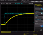
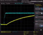
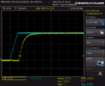
I did some measurements with different values of C7 at reset circuit. I also put a 100 ohms resistor in series to it.

Here are the transient responses where yellow is the input voltage and blue is the reset voltage.

C7=1uF, series 100ohm resistor added:
New-Design-Trans.PNG Zoomed version:New-Design-Zoom.PNG


Old design with C7=100nF:
Old-Design-Trans.PNG


I also changed C7 as 10uF, but it did not solve the problem, raising sope of reset voltage decreased.

So, should I still be thinking that this problem is caused due to the early reset?

Note: The old design has a completely different power stage design, I cans post if needed.

I've also found out that crystal frequency is more parasitic than the old design. Can this be related to the issue?

Thanks,
Ogulcan
 
Last edited:

Here are the transient responses where yellow is the input voltage and blue is the reset voltage

The reset voltage should arise after the Vcc, these are the nodes you should concern; Try dramatically increasing the value of the reset capacitor or resistor. Anyway, what exactly do you mean by 'input' voltage ?
 

Status
Not open for further replies.

Similar threads

Part and Inventory Search

Welcome to EDABoard.com

Sponsor

Back
Top