Continue to Site

Welcome to EDAboard.com

Welcome to our site! EDAboard.com is an international Electronics Discussion Forum focused on EDA software, circuits, schematics, books, theory, papers, asic, pld, 8051, DSP, Network, RF, Analog Design, PCB, Service Manuals... and a whole lot more! To participate you need to register. Registration is free. Click here to register now.

Two 12-bit ADCs SPI Coding with ATmega128 MCU

Status
Not open for further replies.

musmanm

Member level 2
Member level 2
Joined
May 7, 2015
Messages
50
Helped
0
Reputation
0
Reaction score
0
Trophy points
6
Location
Seoul
Visit site
Activity points
558
Hello everyone!

I am very new to coding, especially for an application like this. My system needs data acquisition and processing and simultaneously displaying results on a 16x2 character LCD screen.

I have an RF return loss measurement system. I have to display the return loss on LCD screen on the same PCB board. There are two 12-bit ADCs (ADS7042) and the MCU I have is ATmega128.

ADC1 gives CODE (forward) = CODE_F
ADC2 gives CODE (reflected) = CODE_R

Both CODES have to be processed at the same time.

The equation to calculate return loss values in real time from the two ADCs codes is given as:

2018-01-20_232222.png

This equation has to be processed real-time for every different input, there will be two changed ADC codes and hence a different return loss value for every input.

The both ADCs has to simultaneously transmit digital data to ATmega128 via SPI communication protocol.

I want to code in C and I have just installed AVR Studio 4.

Can someone guide me on how to make a C code for SPI communication in this scenario or is there already some code which I can use for this application?

Thank you in advance.
 

Hi,

I'm confused.
Please give a signal flow diagram with description.

****
You speak about RF...but the ADCs are for 1Msmpl/s only.
I doubt that the ADC input really is RF...so what is it really?

Then you spaek about simultaneously data acquisition and processing.
You can't process them simultaneously, because the ATmega128 is no dual core processor. You need to process one after the other.
Theoretically you could do simultaneous sampling. But then I assume you need to do a soft-SPI with two data channels.
But is this really necessary? If the ADC inputs change relatively fast, then a LCDisplay is not very useful because your brain can't process much more readings than 3 in a second.

Then the formula isn't optimized for an 8 bit microcontroller.
If you square a 12 bit vlaue, the the result will be a 24 bit value.
Why don't you avoid the squaring by: returnloss = 20 × log(Code_F / Code_R)

Klaus


Hello Mr. Klaus,

Thanks for your reply.

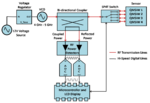
The input to ADC is coming from an RF power detector ADL6010. The complete block diagram of system is attached below:

Proposed Functional Block Diagram.png

Two powers are coming from directional coupler (coupled/forward and reflected). Both powers are going into two RF detectors and then the put of RF detector is an analog voltage which goes into two 12-bit ADCs sampling at 1MSPS. Both ADCs with SPI will be connected to ATmega128.

A little delay can be acceptable, but I want to process return loss equation in real-time. Moving variable resistor knob produces different voltages from 1V-11V and hence the VCO is fed this variable voltage to produce frequencies in between 4GHz to 5GHz. The RF sensors/resonators connected on the right top part operate in between 4-5GHz and thus at resonators operating frequency, the return loss is maximum (high forward power and low reflected power). The max. return loss value after rotating the knob completely will be stored and will go into another equation (permittivity detection equation). For now, we only need to display return loss on the LCD screen which will keep on changing as the rotation knob changes.

I am attaching the picture of hardware here too:

KakaoTalk_20171208_215324406.jpg

And yes we can use simplified return loss equation, as mentioned by you above (avoiding squares).

I am really very new to coding and I am not sure what soft-SPI is.

I would really need your help in organizing the DSP structure of this project. My MCU knowledge is very weak, being from RF background.

Thank you for understanding my project and helping.
 

ATmega can't process ADC data at MS/s. Considering the respective calculations, you'll rather end up at kS/s or below. That's no principle problem for the application, VCO scan speed has to be adjusted appropriately. Not sure if the application requires a particular scan speed respectively measurement points per second.

I see that ATmega hardware SPI doesn't allow exact simultaneous sampling with the chosen ADCs. There are several solutions depending on the effective sampling rate, e.g. using a different ADC type, analog S/H, low-pass filters for quasi simultaneous sampling, mentioned soft SPI.
 
Hi,

This clears up a lot.

and then the put of RF detector is an analog voltage which goes into two 12-bit ADCs sampling at 1MSPS.
I assume the ADC input is very low frequency... and thus they can be treated like DC voltage? Is this true?

Why 1MSmpl/s?
An ATMega can hardly do this.
****

A little delay can be acceptable
I tried to input "a little" into my calculator, but it didn´t accept it.
"A little delay" can be 1° of your 5GHz signal, which is just 0.55ps....I assume this is not what you need.
Maybe you should give some values with units.
****

but I want to process return loss equation in real-time.
You need to specify what means "real time" for you.

An audio application usually is "real time", because all input data are processed in real time.
But "real time" doesn´t say about latency.
So if you are watching TV but the audio output is "delayed" by 1 second, then surely it is "real time" audi processing, but you may find the picture-to-audio delay not satisfying.
(even worse, if the picture is delayed with respect to the audio)

In your case: With the LCD output...you won´t update the display more than 3 times per second. So you have 333ms of time to process the incoming information and display the result.
If the ADC_input signals are fluctuating (synchronously to each other) then you need to specify this (frequency or dv/dt)....and the max tolerable error caused by this.

Consider this:
If the values considerably fluctuate between two display_updates (333ms?), then you (or your brain) won´t be able to trace this. Then a graph or a scope is more useful to trace the fluctuation.

***
Soft-SPI:
Software SPI (in opposite to hardware SPI).
The AVR internal SPI can´t work with two ADCs in parallel.
The only way I see (if you really need this) is to "emulate" the SPI function with software. A lot of code. No precise timing. Try to avoid it.

***
DSP structure:
A big phrase. But a small task in your case:
ADC-sampling, dividing, logarithm...

****
Please understand:
As long as you move the knob: you don´t need high resolution, nor high precision. Jou just wnt to see if the value goes up, down or doesn´t move.
But I assume when the knob is not moved you want precise values.
This can be optimized by using low pass filters - either analog or digital. No big deal.

Klaus
 
Hi,


I assume the ADC input is very low frequency... and thus they can be treated like DC voltage? Is this true?
Yes, the ADC input can be treated as DC voltage. It should not fluctuate at one particular frequency (when the knob is not moving). The input to ADC is from 4V max to 4mV minimum. Moving when the knob is moving.

Why 1MSmpl/s?
An ATMega can hardly do this.
****
Because I was wondering if the data will be sampled and processed quickly enough, keeping in mind the knob rotation from 1V to 11V in 10-15 seconds.

I tried to input "a little" into my calculator, but it didn´t accept it.
"A little delay" can be 1° of your 5GHz signal, which is just 0.55ps...I assume this is not what you need.
Maybe you should give some values with units.
****
Knob rotation from 1V to 11V in 10-15 seconds. Displaying one result in one second on LCD will do the job too.

You need to specify what means "real time" for you.
As mentioned above. From real-time, I meant knob rotation from 1V to 11V in 10-15 seconds. Displaying one result in one second on LCD will do the job too.

An audio application usually is "real time", because all input data are processed in real time.
But "real time" doesn´t say about latency.
So if you are watching TV but the audio output is "delayed" by 1 second, then surely it is "real time" audi processing, but you may find the picture-to-audio delay not satisfying.
(even worse, if the picture is delayed with respect to the audio)

In your case: With the LCD output...you won´t update the display more than 3 times per second. So you have 333ms of time to process the incoming information and display the result.

If the ADC_input signals are fluctuating (synchronously to each other) then you need to specify this (frequency or dv/dt)....and the max tolerable error caused by this.

ADC input signals are stable when knob is not rotating. There will be one fixed return loss value at one single frequency.

Consider this:
If the values considerably fluctuate between two display_updates (333ms?), then you (or your brain) won´t be able to trace this. Then a graph or a scope is more useful to trace the fluctuation.

***
Soft-SPI:
Software SPI (in opposite to hardware SPI).
The AVR internal SPI can´t work with two ADCs in parallel.
The only way I see (if you really need this) is to "emulate" the SPI function with software. A lot of code. No precise timing. Try to avoid it.

I see. I thought SPI communication protocol is fast, uses duplex mode of communication and is reliable using ADCs.

***
DSP structure:
A big phrase. But a small task in your case:
ADC-sampling, dividing, logarithm...
****
Yes, that's all I need to do. But, I think I need to select another ADC which can work for this application. As 1MSPS seems quite a lot for ATmega128 MCU. Can you please recommend an ADC for this application?

Please understand:
As long as you move the knob: you don´t need high resolution, nor high precision. Jou just want to see if the value goes up, down or doesn´t move.
But I assume when the knob is not moved you want precise values.
This can be optimized by using low pass filters - either analog or digital. No big deal.

Klaus

I can use RC low-pass filter at the input of the ADCs. Do I still use low-pass filters when there are no fluctations (knob being stationary)?

- - - Updated - - -

ATmega can't process ADC data at MS/s. Considering the respective calculations, you'll rather end up at kS/s or below. That's no principle problem for the application, VCO scan speed has to be adjusted appropriately. Not sure if the application requires a particular scan speed respectively measurement points per second.

I see that ATmega hardware SPI doesn't allow exact simultaneous sampling with the chosen ADCs. There are several solutions depending on the effective sampling rate, e.g. using a different ADC type, analog S/H, low-pass filters for quasi simultaneous sampling, mentioned soft SPI.

Thanks for your reply.

Knob rotation from 1V to 11V in 10-15 seconds. Displaying one result in one second on LCD will do the job.

Moreover, if 1MS/S ADC is over spec for this application, can you please recommend me an ADC which may be considerably better as per ATmega128 MCU.

Low-pass filter at the input of an ADC can be designed, to avoid fluctuations. ADC input signals are stable when the knob is not rotating. There will be one fixed return loss value at one single frequency (I expect).
 

ADS7042 sampling rate is controlled by the SPI frame rate, there's no problem to use it at lower speed. Its supply and interface voltage is however limited to 3.3V, it needs level translation to work with ATmega128. Thus I wonder if you won't use a 5V capable ADC?
 

By level translation do you mean the detection limit? 3mV to 3V is the input analog voltage (DC) range to ADC.

Secondly, is it a bad idea to use a 3.3V ADC with a 5V MCU? I was thinking the supply voltages does not matter as I have a power circuit in my system which has 12V to 5V and 5V to 3.3V voltage convertors.

The VCO also needs 3.3V VCC. Though its tuning voltage is from 1V to 11V.
 

I'm referring to level translation for the SPI interface.

Matching the analog input voltage is another thing, but usually performed by simple resistor networks.
 
Hi,

Because I was wondering if the data will be sampled and processed quickly enough, keeping in mind the knob rotation from 1V to 11V in 10-15 seconds.
If you update the display once per second, then an ADConversion once per second could be sufficient.
For sure I'd use multiple samples to reduce noise...but I personally think that 1MSmpl/s gives no benefit.

Instead of two ADCs I'd go for a single ADC with multiplexed input. You could go for two conversions within 10us. The deviation in time and the resulting deviation in voltage should be no problem. Especially when the knob is not moved.
Are you sure you need an external ADC? Isn't the AVR internal 10 bit ADC enough?

Did you consider to use V_F as ADC_Vref .... and V_C as ADC input? (Only possible if always: V_F >= V_C)
Then you need a single cinversion only (where both channels are treated simultaously) and the result is the quotient of both...so you save processing time. Additionally you always get a good resolution fir the quotient.

Can you please recommend an ADC for this application?
I'd start with the AVR internal ADCs.

Do I still use low-pass filters when there are no fluctations (knob being stationary)?
For non-fluctuating input signals the lowpassfilter does nothing. It won't modify the signal.
But since (in my eyes) the LPF makse sense when the knob is moved...I'd use it. No need to switch it off.

Klaus
 
I'm referring to level translation for the SPI interface.

Matching the analog input voltage is another thing, but usually performed by simple resistor networks.

ADC choice is still in my hands. I can choose a 5V ADC to avoid extra circuitry for doing the level translation.

- - - Updated - - -

I'm referring to level translation for the SPI interface.

Matching the analog input voltage is another thing, but usually performed by simple resistor networks.

ADC choice is still in my hands. I can choose a 5V ADC to avoid extra circuitry for doing the level translation.

- - - Updated - - -

Hi,


If you update the display once per second, then an ADConversion once per second could be sufficient.
For sure I'd use multiple samples to reduce noise...but I personally think that 1MSmpl/s gives no benefit.

Instead of two ADCs I'd go for a single ADC with multiplexed input. You could go for two conversions within 10us. The deviation in time and the resulting deviation in voltage should be no problem. Especially when the knob is not moved.
Are you sure you need an external ADC? Isn't the AVR internal 10 bit ADC enough?

Did you consider to use V_F as ADC_Vref .... and V_C as ADC input? (Only possible if always: V_F >= V_C)
Then you need a single cinversion only (where both channels are treated simultaously) and the result is the quotient of both...so you save processing time. Additionally you always get a good resolution fir the quotient.


I'd start with the AVR internal ADCs.


For non-fluctuating input signals the lowpassfilter does nothing. It won't modify the signal.
But since (in my eyes) the LPF makse sense when the knob is moved...I'd use it. No need to switch it off.

Klaus

Now, I also think that 1MSPS is not needed but 12-bit resolution is required, because at times the reflected voltage from one of the RF power detector becomes really low (around 2mV) and ATmega128's internal ADCs are 10-bit and if we calculate its resolution as per 5V. It becomes 5/1024 = 4.8mV. So, by keeping the lower limit of voltage in mind, I wanted to have a 12-bit ADC (external).

I will use LPF in my circuit design too.

A multi-input ADC seems an interesting choice. It will reduce an extra component on my system, which is good. But again, the two incoming analog voltages on ADC input are not similar. They are both different and have different upper and lower limit (range). Reflected voltage sometimes goes as low as nearly 2mV (at resonant frequency).
 

Hi,

3.3V vs 5V:
Why not run the ATMega with 3.3V?

Klaus

Hi,

ATmega128 can run from 4.5 - 5.5V (written in datasheet). I have also ordered the evaluation kit of ATmega128 MCU. Therefore, I do not want to change MCU, but I can change ADC.

I was just ready about this ADC:
https://www.analog.com/en/products/analog-to-digital-converters/ad7091r-2.html#product-overview

It seems AD7091R-2 is a two channel 12-bit ADC. Seems nice and has SPI support too. But again, it also has 1MSPS which we do not need.

- - - Updated - - -

Hi,

ATmega128 can run from 4.5 - 5.5V (written in datasheet). I have also ordered the evaluation kit of ATmega128 MCU. Therefore, I do not want to change MCU, but I can change ADC.

I was just ready about this ADC:
https://www.analog.com/en/products/analog-to-digital-converters/ad7091r-2.html#product-overview

It seems AD7091R-2 is a two channel 12-bit ADC. Seems nice and has SPI support too. But again, it also has 1MSPS which we do not need.

It also can be operated on 5V voltage which is same with ATmega128

- - - Updated - - -

Hi,

ATmega128 can run from 4.5 - 5.5V (written in datasheet). I have also ordered the evaluation kit of ATmega128 MCU. Therefore, I do not want to change MCU, but I can change ADC.

I was just ready about this ADC:
https://www.analog.com/en/products/analog-to-digital-converters/ad7091r-2.html#product-overview

It seems AD7091R-2 is a two channel 12-bit ADC. Seems nice and has SPI support too. But again, it also has 1MSPS which we do not need.

- - - Updated - - -


It also can be operated on 5V voltage which is same with ATmega128

But it has a 50MHz clock speed and the ATmega128 has a 16MHz clock speed. Can the ADC clock speed get adjusted or reduced?
 

Hi,

Yes, ATMega128 is for 5V only. You can't use ATMega128L?

AD SCLock is specified with 50MHz max.
You may use lower frequency clock.

Klaus
 
Hi,

I can use ATmega128L to work on 3.3V but then how can I control the SP4T switch?

That switch in the block diagram needs logic of 0V-0V, 0V-5V, 5V-0V and 5V-5V to change the states among the 4 resonators.

That needs 5V and also its operating voltage is -5V (using invertor IC to produce -5V)

Also the LCD works with 5V.

I know there may be techniques to work a 3.3V MCU with 5V components but I am trying to reduce the circuit components as much as I can too.

Therefore, ATmega128 and its evaluation board is already on its way.

Did you read AD7091R-2 ADC and do you recommend me to use this ADC for this job? It works on 5V also and has dual input channels for my two incoming powers. Supports SPI and also has 12-bit resolution.
 

Hi,

A riddle.... What SP4T switch are you talking about?

Usually an analog switch has logic inputs...and no logic outputs.
And often the analog inputs work with TTL input levels.
So it is happy with the output levels from a 3.3V supplied CMOS device like the AVR.

You (as well as every electronics designer) need to read datasheets:
At the SP4T datasheet look for: V_IL and V_IH.
And at the AVR datasheet look for V_OL and V_OH.
Usually you find them in the specification tables for "I/O"s. No need to read the complete datasheet for these informations.

Klaus
 
Hi,

A riddle.... What SP4T switch are you talking about?

Usually an analog switch has logic inputs...and no logic outputs.
And often the analog inputs work with TTL input levels.
So it is happy with the output levels from a 3.3V supplied CMOS device like the AVR.

You (as well as every electronics designer) need to read datasheets:
At the SP4T datasheet look for: V_IL and V_IH.
And at the AVR datasheet look for V_OL and V_OH.
Usually you find them in the specification tables for "I/O"s. No need to read the complete datasheet for these informations.

Klaus

The IV_L is 0V to 3V and IV_H is 4.2V to 5V for this SP4T switch. In datasheet these voltages are all in negative but because the switch has internal binary decoder, connected to -5V VEE, we can supply 0V to 3V (positive) as low and 4.2V to 5V (positive) as high.

The link of the SP4T switch is here:
https://www.analog.com/en/products/rf-microwave/rf-switches/spst-spdt-sp3t-sp4t-sp6t-sp8t/hmc344a.html#product-overview

In ATmega128 datasheet:
V_OL: 0 to 0.7V
V_OH: 4.2 to 5V

Therefore, in my point of view, this SP4T switch can work well with ATmega128 MCU.

Can I use this ADC mentioned above?
AD7091R-2
 

Hi,

Honestly, I don't know how you decided to control the switch.....with the negative voltages...

Klaus
 

Status
Not open for further replies.

Part and Inventory Search

Welcome to EDABoard.com

Sponsor

Back
Top