Continue to Site

Welcome to EDAboard.com

Welcome to our site! EDAboard.com is an international Electronics Discussion Forum focused on EDA software, circuits, schematics, books, theory, papers, asic, pld, 8051, DSP, Network, RF, Analog Design, PCB, Service Manuals... and a whole lot more! To participate you need to register. Registration is free. Click here to register now.

[SOLVED] Difference between the Schematics of MOS varactors

Status
Not open for further replies.

umberabbas

Member level 1
Member level 1
Joined
Mar 24, 2017
Messages
32
Helped
0
Reputation
0
Reaction score
0
Trophy points
6
Activity points
285
I want to use varactors to get the tuning curves but I am confused as to which varactor should be chosen among the available. Also, can the varactor type be identified by looking at the schematic? Attached is the figure for the reference. It's a NMOS varactor but is it a accumulation or an inversion MOS? vrac.png
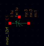
please also describe how to simulate this varactor to get Cg/Vg or Cg/Vtune curves?
 

I want to use varactors to get the tuning curves
but I am confused as to which varactor should be chosen among the available.
No one can know what varactor are available except for you.

Also, can the varactor type be identified by looking at the schematic?
No.
See layout and masks.

please also describe how to simulate this varactor to get Cg/Vg or Cg/Vtune curves?
Do AC analysis of single frequency point with sweeping Vg.
 

There ought to be a library document telling you the
applications purposes, device details, constraints and
performance of the elements. This may be a "modeling
document" or it may be a "device applications guide"
but any well run CAD group would have this kind of
collateral either bundled with the PDK or available for
download on foundry support pages.

You may care about other things than C and voltage
range, for example series R and L. That all depends a
lot on the layout details as well as operating point and
device vertical construction.
 

Please have a look and let me know whether I am doing it right or not.vrac1.pngnetlist1.pnggraph1.png
 

What value do you apply as "vctrl" ?

And what are "net4" and "net03" ?

I assume MOS varactor of attached figure.

Is "net4" "G" ?
Is "net03" "S/D" ?

Save terminal current of C1.

Then reshow netlist as text not image.
 

Attachments

  • 171123-161713.png
    171123-161713.png
    11.4 KB · Views: 211
Vcntrl and Vs both as 0.1 v.

net03 is the gate to V node and net4 is the node of G to Vg.
graph2.png

-------NETLIST----------
simulator lang=spectre
global 0
parameters vcntrl=100m Vg=100m

View name: schematic

C1 (net4 net03 0) nvar_12rf w=(2u) l=(2u) ny=3 nx=3 m=1

Vg (net4 0) vsource dc=Vg mag=1m type=sine freq=60G

Vcntrl (net03 0) vsource dc=vcntrl type=dc

simulatorOptions options reltol=1e-3 vabstol=1e-6 iabstol=1e-12 temp=27 \

tnom=27 scalem=1.0 scale=1.0 gmin=1e-12 rforce=1 maxnotes=5 maxwarns=5 \

digits=5 cols=80 pivrel=1e-3 sensfile="../psf/sens.output" \

checklimitdest=psf

ac ac freq=60e9 param=Vg start=10m stop=300m step=10 annotate=status

dcOp dc write="spectre.dc" maxiters=150 maxsteps=10000 annotate=status

dcOpInfo info what=oppoint where=rawfile

dc dc param=vcntrl start=10m stop=300m step=0.1 oppoint=rawfile \

maxiters=150 maxsteps=10000 annotate=status

modelParameter info what=models where=rawfile

element info what=inst where=rawfile

outputParameter info what=output where=rawfile

designParamVals info what=parameters where=rawfile

primitives info what=primitives where=rawfile

subckts info what=subckts where=rawfile

save C1:1 C1:2

saveOptions options save=allpub
 

vrac3.png

I have labelled the schematic for more clarity. I hope this will be sufficient.
 

test_umberabbas.scs
Code:
// Generated for: spectre
// Generated on: Nov 24 10:45:50 2017
// Design library name: kkk
// Design cell name: test_umberabbas
// Design view name: schematic
simulator lang=spectre
global 0
parameters Vg=1 Vsd=0 my_freq=1G
include "ttt.scs"

// Library name: kkk
// Cell name: test_umberabbas
// View name: schematic
L1_feed1 (G net05) dcfeed l=1u
L1_feed2 (SD net03) dcfeed l=1u
V1 (net03 0) vsource dc=Vsd type=dc
V0 (net05 0) vsource dc=Vg type=dc
PORT2 (net052 0) port r=100K num=2 type=dc
PORT1 (net07 0) port r=100K num=1 type=dc
C1 (G SD 0) moscap_rf_nw wr=2.5u lr=0.5u br=10 gr=2
C1_block1 (G net07) dcblock c=1u
C1_block2 (SD net052) dcblock c=1u
simulatorOptions options reltol=1e-3 vabstol=1e-6 iabstol=1e-12 temp=25.0 \
    tnom=25.0 try_fast_op=no scalem=1.0 scale=1.0 gmin=1e-12 rforce=1 \
    maxnotes=5 maxwarns=5 digits=5 cols=80 pivrel=1e-3 \
    sensfile="../psf/sens.output" checklimitdest=psf 
sp sp freq=my_freq param=Vg start=-1 stop=1 lin=1000 annotate=status 
designParamVals info what=parameters where=rawfile
saveOptions options save=allpub pwr=none currents=all

Skill Code Fragments for Post Processing
Code:
omega = 2 * acos(-1) * VAR("my_freq")
z11 = zpm('sp 1 1)
z12 = zpm('sp 1 2)
z21 = zpm('sp 2 1)
z22 = zpm('sp 2 2)
Z1_diff = (z11 + z22) - z12 - z21
C1_diff = imag(1 / Z1_diff) / omega
 

Attachments

  • 2017-1124-1044-54.png
    2017-1124-1044-54.png
    76.1 KB · Views: 216
  • 2017-1124-1045-31.png
    2017-1124-1045-31.png
    45.7 KB · Views: 237
Last edited:
Thank you a million times. You are a lifesaver :) :)
 

Status
Not open for further replies.

Part and Inventory Search

Welcome to EDABoard.com

Sponsor

Back
Top