Continue to Site

Welcome to EDAboard.com

Welcome to our site! EDAboard.com is an international Electronics Discussion Forum focused on EDA software, circuits, schematics, books, theory, papers, asic, pld, 8051, DSP, Network, RF, Analog Design, PCB, Service Manuals... and a whole lot more! To participate you need to register. Registration is free. Click here to register now.

long distance cell phone detector

Status
Not open for further replies.

000SHREDDER000

Full Member level 1
Full Member level 1
Joined
Apr 9, 2017
Messages
96
Helped
0
Reputation
0
Reaction score
0
Trophy points
1,286
Visit site
Activity points
1,975
Hi guys I am alvin new here, can someone help to me to solve this circuit problem? I found this schematics on circuitdiagram website after building it many time it doesn't work correctly, circuit designer claims this circuit can detect cellphone waves from long distance but when I test it I didn't saw any detection
led is always on
I tried to make different designs with same components but none of them worked
some designs only detect human body!!! from near distance,

so what do you think about this circuit and how can I fix it? tank you:thinker:

Here is schematic:
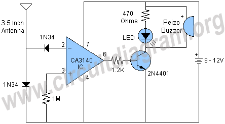
3320534100_1491764370.gif


[found at http://www.circuitdiagram.org/long-range-cell-phone-detector.html ]
 
Last edited by a moderator:

Hi,

I was unable to simulate this circuit accurately, so couldn't say if it works or not. I would have thought that phone signals are in the standard ranges (450 to 2,000MHz and some well beyond that), so I really couldn't say if that general purpose transistor and that specific op amp are capable of functioning at that speed, for a start - the CA3140 is 15MHz GBW, so scale that back sensibly and I personally doubt it can function at more than e.g. 5MHz...; and the buzzer needs a squarewave or sinewave to make the buzzing sound; also, not sure why the LED needs to be operated at 15mA (9V) or 21mA (12V) - what a waste of a battery; and, knowing nothing about antennas, I suppose they generate tiny voltages, maybe not enough to get past the diode to the op amp input.

I'm probably wrong about some of this conjecture.

If you have an oscilloscope, make a call or send a text next to the antenna - if nothing happens then perhaps there is an error in the implementation and/or layout, or perhaps it is one of those circuits which worked for the designer but may not work for all people who copy it.

If the 3140 is completely like the 741, whose output is always well above the Vbe of that transistor, with or without any input, the LED will always be on.
 

??? the op-amp doesn't amplify at signal frequency, it just looks for rectified RF from the diodes.

The circuit is completely unselective and can trigger on static or any other interference, it isn't well thought out. It probably will work over short distances but 'long distance' could be a short as a few metres away depending on surrounding and background noise. Even adding a simple tuned circuit at the input would make it far more sensitive and less prone to false triggering. There is also a somewhat 'hit and miss' approach to the op-amp inputs, the output could adopt an almost random state without any negative feedback being used.

Brian.
 
  • Like
Reactions: d123

    d123

    Points: 2
    Helpful Answer Positive Rating
??? the op-amp doesn't amplify at signal frequency, it just looks for rectified RF from the diodes.

The circuit is completely unselective and can trigger on static or any other interference, it isn't well thought out. It probably will work over short distances but 'long distance' could be a short as a few metres away depending on surrounding and background noise. Even adding a simple tuned circuit at the input would make it far more sensitive and less prone to false triggering. There is also a somewhat 'hit and miss' approach to the op-amp inputs, the output could adopt an almost random state without any negative feedback being used.

Brian.
tank you, I will add a tuned circuit soon
 

My first advice would be to ignore "instructables" and similar web sites. I mean no disrespect to the site owners but they are full of technical nonsense and articles written by novices who make ridiculous claims about circuit they experimented with.

If you want a sensitive detector, start with some filtering (a tuned circuit for example) to eliminate the frequencies you dont want, then amplify the remainder and rectify it. Finally, use the rectified voltage to drive a comparator to decide if it is strong enough to be a recognisable phone signal. There is no other way to do it.

Brian.
 
I could not agree more, Brian.

I ignore the exact problem with Instructables, but my feeling is that they are neither edited nor moderated.
Anyone can publish anything, with elementary errors (like the 21mA thru the LED as noted above), which makes me wonder whether the authors even understand Ohm's law.
 

Those are still not 'real' cell phone detectors but they are a huge improvement on the first designs you posted.
Note that they are extremely sensitive to layout, especially around the 'C1' component, you stand absolutely zero chance of it working on breadboard. They are also critical of the IC types and even the same type from a different manufacturer may give different results. The reason is both designs rely on the input circuit of the IC (including it's pin lengths!) to complete the tuned circuit, it utilises parameters of the IC which are not normally specified or guaranteed by the maker. A purpose designed RF front end would make it work better and more reliably.

Brian.
 

The '1458 opamp used in the circuit has a unity gain bandwidth of only 1MHz. I don't know how it can possibly operate up to even 50MHz, yet alone 500GHz as claimed.
 

I doubt that the author has verified detector operation above 10 GHz. As stated, the circuit utilized the nonlinear base-emitter characteristic of the OP differential input pair to rectify RF. But rectifier diode operation is frequency limited, and there are other parameters like bond wire inductance.
 

I doubt that the author has verified detector operation above 10 GHz. As stated, the circuit utilized the nonlinear base-emitter characteristic of the OP differential input pair to rectify RF. But rectifier diode operation is frequency limited, and there are other parameters like bond wire inductance.

you mean the schematic is uncompleted?
why circuit haven't antenna
 

you mean the schematic is uncompleted?
why circuit haven't antenna
The circuit is a cheap "crystal radio" that has terrible sensitivity and when the RF signal is strong enough then its very simple tuning will pickup all radio stations, TV stations and communications at the same time.
 
you mean the schematic is uncompleted?
why circuit haven't antenna

I don't think you understand how it operates. It is NOT a receiver in the conventional sense and the op-amp does not amplify at high frequency. The way it operates is there is a crude tuned circuit made from the wires of the capacitor, essentially they ARE the antenna. When the signal reaches the op-amp inputs it unbalances the input transistors, they don't amplify the signal itself but the disturbance it creates causes a shift in the DC levels they produce. It's that shift that operates your alarm. Using the input of the op-amp in that way is not recommended and it's performance will not be guaranteed. If a different type of capacitor, different wire lengths or even a different brand of op-amp is used, the performance might be quite different. Adding an antenna will probably de-tune it to the point it stops working at all.

A proper receiver isolates the signal you want, amplifies it to a usable level at it's actual frequency then recovers the signal strength by rectifying it. Doing it properly makes it more selective of the frequencies it receives, allows you to add an antenna to improve range and allows you to decide on how strong the signal has to be before the alarm operates.

Brian.
 
The "advanced" version of the first circuit also has no tuned LC and has no RF amplifier. It is so stupid that the battery is in the wrong location and will destroy IC2 because the battery is connected to its pin 3 output. IC1 and IC2 are not properly powered.
 
Also I heard about rms detectors and none rms detectors, can someone explain differences between them?
 

Status
Not open for further replies.

Similar threads

Part and Inventory Search

Welcome to EDABoard.com

Sponsor

Back
Top