sL.
Newbie level 2

- Joined
- Apr 24, 2010
- Messages
- 2
- Helped
- 0
- Reputation
- 0
- Reaction score
- 0
- Trophy points
- 1,281
- Activity points
- 1,299
Hi folks, currently I'm designing a 7-bit DAC with R2R. I have to use Menthor Graphic ELDO to draw the schematic and layout.
Firstly, I have problem with the switches on R2R ckt. I have these 3 ckts (images enclosed). I'm not sure which is the correct 1. If all these ckts are wrong, anyone minds to draw a correct 1 for me?
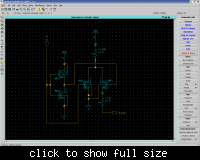
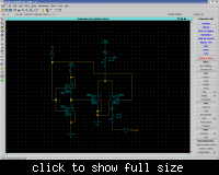
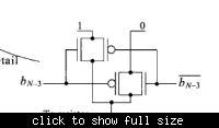
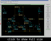
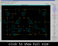
And for the Op Amp part, I did it first with the current sources. I think it worked. But after I draw the real Op Amp (with changes and added CMOS transistors), it fails (2nd Image). I know that the all the transistors must be in saturation to "ON". What is the function and value of Rbias? What is the current across all the ckt? Shoud I adjust the current to the previous value like in Image1? What is the correct output V?
Or anyone has a completed full schematic is welcome to send to me!
I need to come out with something in two days. Hope someone will help in this! Thank you very much!
Firstly, I have problem with the switches on R2R ckt. I have these 3 ckts (images enclosed). I'm not sure which is the correct 1. If all these ckts are wrong, anyone minds to draw a correct 1 for me?


And for the Op Amp part, I did it first with the current sources. I think it worked. But after I draw the real Op Amp (with changes and added CMOS transistors), it fails (2nd Image). I know that the all the transistors must be in saturation to "ON". What is the function and value of Rbias? What is the current across all the ckt? Shoud I adjust the current to the previous value like in Image1? What is the correct output V?


Or anyone has a completed full schematic is welcome to send to me!
I need to come out with something in two days. Hope someone will help in this! Thank you very much!