moro
Member level 3

Hello,
i am working on a school project for controling a 3 phase bldc motor using a microcontroler ( stm32f429)
The motor characteristics can be found in the attached datasheet.
- 6 pole motor
- phase-phase resistance 0.24 Ohm
- PWM frequency is 25 KHZ
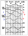
- rotor position is read with via hall sensors
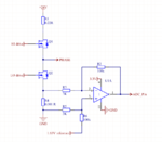
For current measurement i use a 1 miliOhm shunt, buffed by a opamp with a gain of 33.33, and a reference offset of 1.65V
This is how the current voltage at the input of ADC looks like, and the 6 PWMs signals,

Here is a bit zoomed in where you can see the ADC EOC end of conversion flag. Since there is no start of conversion flag, i presume the value is captured right after the rising edge of 1H pwm

I am attaching the current measurement circuit

For the tests i used a dutycycle of 10%.
The ADC capture is triggered by the PWM from the high side transitor.
Using the ADC end of conversion interrupt flag, i store the measured value and send it to the pc where i plot it to matlab
You can see the waveform ploted in matlab from the ADC readout

In the schematic attached i have placed a 0.22 ohm resistor, when the motor is running at 10% duty, i measure around 47mV (0.047V/0.22R = 0.2136A)
So the inverter circuit is drawing arround 213mA from the +24V supply.
Since the motor is having only 2 phases energized at a time, i presume the current trough each commutation period should be the same as on the +24V rail?
Suposing the same current is flowing trough the phase shunt, i should have a voltage of 0.001R x 0.213 A = 213 uV,
Amplified by a Gain of 33.33 i should have a 7.12 mV + 1.650V offset, thus i should read arround 1.657V.
From the matlab plot i can see i have a Peak voltage 1.86V, how can i scale down to get thouse 213mA from the measured voltage?
I tried to get the offset out, so 1.86 - 1.65 = 0.21 V
So in my shunt i theoretically read 0.21V/33.33 = 6.3mV, but if i divide this according to ohms law, i get 6.3mV/1mohm = 6.3 Amps!!
I also tried to see if the rms value fits, so ( 6.3mV x 0.707) / 1mOhm, but stil i get 4.45Amps, which is far away from the 210mA
I have very little experience with motors, but maybe you can share some light. My fear is that i am missing some thing in the maths
i am working on a school project for controling a 3 phase bldc motor using a microcontroler ( stm32f429)
The motor characteristics can be found in the attached datasheet.
- 6 pole motor
- phase-phase resistance 0.24 Ohm
- PWM frequency is 25 KHZ
- rotor position is read with via hall sensors
For current measurement i use a 1 miliOhm shunt, buffed by a opamp with a gain of 33.33, and a reference offset of 1.65V
This is how the current voltage at the input of ADC looks like, and the 6 PWMs signals,

Here is a bit zoomed in where you can see the ADC EOC end of conversion flag. Since there is no start of conversion flag, i presume the value is captured right after the rising edge of 1H pwm

I am attaching the current measurement circuit

For the tests i used a dutycycle of 10%.
The ADC capture is triggered by the PWM from the high side transitor.
Using the ADC end of conversion interrupt flag, i store the measured value and send it to the pc where i plot it to matlab
You can see the waveform ploted in matlab from the ADC readout

In the schematic attached i have placed a 0.22 ohm resistor, when the motor is running at 10% duty, i measure around 47mV (0.047V/0.22R = 0.2136A)
So the inverter circuit is drawing arround 213mA from the +24V supply.
Since the motor is having only 2 phases energized at a time, i presume the current trough each commutation period should be the same as on the +24V rail?
Suposing the same current is flowing trough the phase shunt, i should have a voltage of 0.001R x 0.213 A = 213 uV,
Amplified by a Gain of 33.33 i should have a 7.12 mV + 1.650V offset, thus i should read arround 1.657V.
From the matlab plot i can see i have a Peak voltage 1.86V, how can i scale down to get thouse 213mA from the measured voltage?
I tried to get the offset out, so 1.86 - 1.65 = 0.21 V
So in my shunt i theoretically read 0.21V/33.33 = 6.3mV, but if i divide this according to ohms law, i get 6.3mV/1mohm = 6.3 Amps!!
I also tried to see if the rms value fits, so ( 6.3mV x 0.707) / 1mOhm, but stil i get 4.45Amps, which is far away from the 210mA
I have very little experience with motors, but maybe you can share some light. My fear is that i am missing some thing in the maths


