Continue to Site

Welcome to EDAboard.com

Welcome to our site! EDAboard.com is an international Electronics Discussion Forum focused on EDA software, circuits, schematics, books, theory, papers, asic, pld, 8051, DSP, Network, RF, Analog Design, PCB, Service Manuals... and a whole lot more! To participate you need to register. Registration is free. Click here to register now.

how to interface a current transformer to pic16f877a to measure the current ?

Status
Not open for further replies.

Prabhu Siva

Newbie level 5
Newbie level 5
Joined
Aug 12, 2015
Messages
10
Helped
0
Reputation
0
Reaction score
0
Trophy points
1
Activity points
77
Actually i need to interface the pic16f877a with current transformer to measure the current flow to the compressor. when the current consumption is more i need to turn it off so i need to measure the current . kindly help me in program in pic16f877a


thanks in advance
 

Hi,

You don't say anything about current and voltage...so we have to guess...
There are many current transformers.
If you use a passive one it has a current transfer ratio.
Maybe 1000:1. It means if you have 10A input current, then it has 10mA output current.
Let's say you want an input range of 10A AC, then you have +/- 14A voltage range --> +/- 14mA output current.
Now if your PIC ADC input voltage range is 3.0V you need a resistor of 3V/28mA = about 100 Ohms.
Additionally you need a voltage divider to lift the transformer output to VRef/2.
I recommend to use low pass filter between transformer and ADC.

Klaus


I need to measure the current flow to the compressor if the compressor is consuming more amount of current i need to switch off the compressor. the compressor is consuming 28amps right now if it starts to consume above 30amps i need to switch of it.
 

You would convert current to voltage for measurement.

v=ir

for a example

CT = 50/1A. 50/1A means that if 50 amps currnt will flow in primary then 1 amps current will flow in secondary. Actually it is the transformation ratio of the ct Ip/Is. Second you will use a voltage divider.

r = v/i
r = 5/1 = 5E

i am using pic16f877a controller so it required current only in milli amps, from your input i decided that i need to choose the current transformer with a ratio of 30:5milliamps. but i need to how to configure with pic16f877a USING voltage divider bias and the concept of calculating rms current rms can u help in designing the schematic diagram to interace the CT
 

Hi,

I doubt the circuit shown in the link above gives (good) results...

***
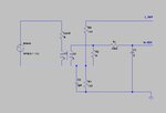
Better use this:
curMeas.jpg
* CT/L2 is the current transformer. You need to know transfer ratio
* R2 is for setting output voltage
* R3 & R4 & C2 are for biasing output signal to V_Ref/2. Center of ADC value is zero. Below center is negative current, above is positve current.
* R1 & C1 form a low pass filter (used for attenuate high frequency, to lower noise level, as anti aliasing filter)

Klaus
 
Status
Not open for further replies.

Similar threads

Part and Inventory Search

Welcome to EDABoard.com

Sponsor

Back
Top