Continue to Site

Welcome to EDAboard.com

Welcome to our site! EDAboard.com is an international Electronics Discussion Forum focused on EDA software, circuits, schematics, books, theory, papers, asic, pld, 8051, DSP, Network, RF, Analog Design, PCB, Service Manuals... and a whole lot more! To participate you need to register. Registration is free. Click here to register now.

Help Identifying PCB

Status
Not open for further replies.

wireman121

Newbie level 5
Newbie level 5
Joined
Oct 13, 2014
Messages
9
Helped
0
Reputation
0
Reaction score
0
Trophy points
1
Visit site
Activity points
57
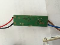
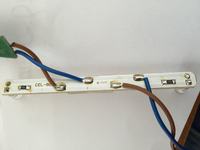
I have been tasked with reproducing a simple LED circuit which consists of 3 PCBs. I am unable to idenfity what the components are doing on the power supply board and was hoping for a little help on it. I am not married to reproducing this circuit verbatim, I just need the same result of controlling the 4 LEDs with either 3 AA batteries or 1 9V battery. I was planning on using Pad2Pad.com to print the boards and digikey for the components, once I know what I am designing here. Any help would be greatly appreciated!
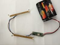
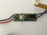
 
Last edited by a moderator:

74LVC1G74 and some sort of DPack logic level mosfet would be my guess, but it feels right.

Leds in parallel with individual series resistors, '74 wired to toggle when the switch is pressed (It might be a S/R latch of some sort would make the debounce simpler, who knows), mosfet as a power switch.

Why would anyone want to reverse something like this, almost certainally quicker just to sketch it out from scratch.

Regards, Dan.
 

I think the small 6-pin chip is a max16054 or similar. My guess is that it is controlling the latching circuit of the momentary push by the pushbutton.

I'm also assuming the other chip is a voltage regulator, 5v? 3v? not sure yet.
 

hah. This is my first project ever, so I would be more than happy sketching it from scratch - would you be willing to help me out? I have more than enough solder experience, but I've never designed a PCB before, or CHOSE which components go into a circuit, I've just built predesigned things before....

It is simple enough that I just need a momentary pushbutton to latch the LEDs on or off...

- - - Updated - - -

does this diagram look like that I have/what I can use?
http://www.discovercircuits.com/PDF-FILES/On-OFFFlipFlop1.pdf
 

Thats the sort of idea, mine would have been slightly different in detail (Slightly lower parts count), but the principle is the same and that one should probably work ok.

Do note the 6V upper limit, this will not be reliable on 9V, but will be fine on 3 AA cells (4.5V).

Regards, Dan.
 

I created that circuit in Pad2Pad. Not sure if I did it right. I was trying to figure out how to use a ground plane but it wouldn't work right so I gave up. I'm assuming this circuit will replace the green board in the pictures above. Attached is the LED board which I think is pretty straight forward.

How did I do?
 

Attachments

  • PCBs.zip
    10 KB · Views: 49
Last edited by a moderator:

How exact must the duplicate be? Form, Fit or Function? Or just simlilar.

5mm White LEDs have a forward forvate of 2.8V at low current and the internalm series resistance varies with current but is approx 12-24 Ohms at typ. Rating of 20mA

Thus the forward voltage increases with current caused a variation in range in devices for the typical device, which varies but has a Vf of 3.2 @20mA. This fact results of the rise in Vf always rated at 20mA for this type.

Thus when calculating the current for a battery which drops voltage during life discharge, you would use the minimum Vf + Rs or internal "effective series resistance" (ESR) which rises for dropping current, but we can use a fixed value for,determining how much extra R is required for a simple current limiter.

Thus since 3AA cells works well for the 3V white LED, we should use this.

The 9V cell composed of 6 smaller 1.5V cells, or twice the voltage, so if that was selected you could only choose 2LEDs in series with two series strings in parallel. Being a smaller battery, it will have a somewhat smaller capacity than 3AA's and a shorter LED run time, with 2x20mA for 4 LED's@9V than 3AA cells @4.5V supplying 4x20mA.

There are many simple latches.

1. a counter using the least significant bit or last 2 bits, 00,01,10,11, repeating.
2. An RS flip flop(FF) , a D FF,
3.. A pair of inverting gates to make an RS flip flop.

Let's Consider the 3rd.
01349x01.png


But how much extra current can we expect from a Gate?
Depends of the Logic family and internal,resistance.
How do you estimate the internal resistance?
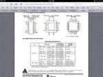
From the data-sheet for Vol/I for selected Vcc for V output Low and (Vcc-Voh)/I for output high.
image.jpg
image.jpg
Can you calculate the ESR of the 'LVC2G02?
I get a diff. value for High and low.
For Vol , ESR=17 Ohms and for Voh, ESR=22.

But these are more than the 5mm LED, but remembering both values will be useful in choosing serial or parallel strings of LEDs and deciding if you want to drive from the low side or high side.

It doesn't matter much in these parts, does in others. 'LVC2G series are pretty low in the whole CMOS family.

Choosing the current 20mA, we can get away with LEDs from the same batch in parallel wIth either driving two with 1 resistor and the other two LEDs with another 1 series resistor.

Thus for fresh battery voltages, 4x1.65=6.6V

We get using the the high side, Voh ESR=22 and two LEDs in parallel, Vf ESR=16 Ohms average /2 = 8 Ohms +- 50% (12-24) . You can verify with your LED choice if different but this is close enough.

Thus using the White LED threshold Vth of 2.8V, ( take my word for now) we calc as follows;

What happens if we drive the 4 LEDs direct off the NOR Gate?

At nominal Vbat= 4.5V, Vth=2.8V and the high side 22 ESR , we expect the current would be ;

(Vcc max - Vth)/{ESR total} = (6.6-2.8)/{22+8}= 127mA , which woud exceed the chip 50mA max for Vo. This neglects that batteries also have ESR and could be considered, which may be ~1 ohm per fresh battery.

For Vbat nom , (4.5-2.8)/30=90mA
For Vbat dead , (3-2.8)/30=6.7mA or 1.5mA per LED and very dim.

But,we need to limit the NOR gate current to 50mA for reliability reasons and thermal effects.

SO you have a choice to,add,a simple MOSFET driver or use a Quad NOR gate and share the load.

CAPS are not needed wiche the RS FF is not glitch sensitive as repeated sets do not alter the output.

The original schematic shows two single,complementary LED's but only asked for,.4x with On Off control.
 

Attachments

  • image.jpg
    image.jpg
    681.6 KB · Views: 82

Dan - What components would you cut out of my circuit from Pad2Pad? Is there an easy way for me to order these components, assemble them and test them before actually ordering the PCBs? Since they're almost all surface mount, I think it would be hard to do without a PCB layout setup for them already... I am afraid to change them over to through-hole components for testing as I'm not sure I would be getting the correct crossover parts.....
 

What say you Wireman?
do you want a design to copy or learn how to design a simpler LED driver using CMOS? You can alter my schematic lower LED to drive low side of LED pair while Anode = Vcc and upper LED pair drives Anode as shown with R whilst Cathodes are grounded.

Thus each pair can safely be driven up to 50mA, but 40mA is recommended and thus all 4 are either ON or OFF.

Since S/R requires no debounce unlike Clk input, no caps required on a momentary switch. Also no FET driver Required for upto 50mA per gate and 100mA per chip.
It doesn' get much simpler. 'LVC2G74 FF may also be used, but this is more discrete.

How exact must the duplicate be? Form, Fit or Function? Or just simlilar.

5mm White LEDs have a forward forvate of 2.8V at low current and the internalm series resistance varies with current but is approx 12-24 Ohms at typ. Rating of 20mA

Thus the forward voltage increases with current caused a variation in range in devices for the typical device, which varies but has a Vf of 3.2 @20mA. This fact results of the rise in Vf always rated at 20mA for this type.

Thus when calculating the current for a battery which drops voltage during life discharge, you would use the minimum Vf + Rs or internal "effective series resistance" (ESR) which rises for dropping current, but we can use a fixed value for,determining how much extra R is required for a simple current limiter.

Thus since 3AA cells works well for the 3V white LED, we should use this.

The 9V cell composed of 6 smaller 1.5V cells, or twice the voltage, so if that was selected you could only choose 2LEDs in series with two series strings in parallel. Being a smaller battery, it will have a somewhat smaller capacity than 3AA's and a shorter LED run time, with 2x20mA for 4 LED's@9V than 3AA cells @4.5V supplying 4x20mA.

There are many simple latches.

1. a counter using the least significant bit or last 2 bits, 00,01,10,11, repeating.
2. An RS flip flop(FF) , a D FF,
3.. A pair of inverting gates to make an RS flip flop.

Let's Consider the 3rd.
01349x01.png


But how much extra current can we expect from a Gate?
Depends of the Logic family and internal,resistance.
How do you estimate the internal resistance?
From the data-sheet for Vol/I for selected Vcc for V output Low and (Vcc-Voh)/I for output high.
View attachment 110281
View attachment 110280
Can you calculate the ESR of the 'LVC2G02?
I get a diff. value for High and low.
For Vol , ESR=17 Ohms and for Voh, ESR=22.

But these are more than the 5mm LED, but remembering both values will be useful in choosing serial or parallel strings of LEDs and deciding if you want to drive from the low side or high side.

It doesn't matter much in these parts, does in others. 'LVC2G series are pretty low in the whole CMOS family.

Choosing the current 20mA, we can get away with LEDs from the same batch in parallel wIth either driving two with 1 resistor and the other two LEDs with another 1 series resistor.

Thus for fresh battery voltages, 4x1.65=6.6V

We get using the the high side, Voh ESR=22 and two LEDs in parallel, Vf ESR=16 Ohms average /2 = 8 Ohms +- 50% (12-24) . You can verify with your LED choice if different but this is close enough.

Thus using the White LED threshold Vth of 2.8V, ( take my word for now) we calc as follows;

What happens if we drive the 4 LEDs direct off the NOR Gate?

At nominal Vbat= 4.5V, Vth=2.8V and the high side 22 ESR , we expect the current would be ;

(Vcc max - Vth)/{ESR total} = (6.6-2.8)/{22+8}= 127mA , which woud exceed the chip 50mA max for Vo. This neglects that batteries also have ESR and could be considered, which may be ~1 ohm per fresh battery.

For Vbat nom , (4.5-2.8)/30=90mA
For Vbat dead , (3-2.8)/30=6.7mA or 1.5mA per LED and very dim.

But,we need to limit the NOR gate current to 50mA for reliability reasons and thermal effects.

SO you have a choice to,add,a simple MOSFET driver or use a Quad NOR gate and share the load.

CAPS are not needed wiche the RS FF is not glitch sensitive as repeated sets do not alter the output.

The original schematic shows two single,complementary LED's but only asked for,.4x with On Off control.
 

I made a copy of the link I shared before. Only reason is I need 1 momentary button to latch on and the same button to latch off again. I honestly don't know much about components, especially enough to be able to figure out what needs to be changed... My biggest concern is that I didn't do something right, or used a wrong component somewhere and once I order a ton of these I will be screwed!
 

OK. I think I am starting to understand Pad2Pad and designing... I was able to get everything laid out as best as possible, and also got an order list together on DigiKey. I would feel a TON more comfortable ordering 150 of these if someone with a little more experience could take a look at what I have and make sure it looks right? Thanks for any help!

- - - Updated - - -

Quick note - I realized I had a PMV48XP instead of a PMV65XP in the design, so I updated it. They have the same footprint, but the PMV65XP was not an option in Pad2Pad. My order with Digikey reflects a PMV65XP.
 

Attachments

  • order.pdf
    111.6 KB · Views: 101
  • PCBs Rev 1.zip
    11 KB · Views: 56
Last edited:

Status
Not open for further replies.

Similar threads

Part and Inventory Search

Welcome to EDABoard.com

Sponsor

Back
Top