sinnadyr
Member level 2

Hi there guys and gals!
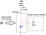
Me and my class mates are making a radon detector and have made PSU, charge and shape amplifier, peak detector, LabVIEW and AVR application and are soooo close to the finish, but still so far away.
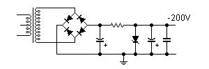
Our PSU is powered by a 17.5V AC adapter (not grounded), transformed up and rectified to 210V DC. This is to get good measurements from our silicon diode detector. The problem is that we do not have a very good lab environment, and is clearly bothered with 50Hz (magnetic?) noise. This ripple is not that big, but is amplified through our circuit and drowns the detector signal, which is only at a few millivolts.
On the PSU output we have a 10µF smoothing capacitor in parrallel to ground, but this does not seem to do the work. Does anyone have any tricks on this?
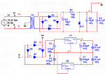
The lower circuit is for powering +/- 5V opamps. The upper part is the PSU that supplies negative 200V.
Any help would be REALLY appreciated! Thanks in advance.
EDIT: Since the +200V is connected to ground to get -200V, may this be a problem? This ground follows the rest of the circuit as 0V reference...
Me and my class mates are making a radon detector and have made PSU, charge and shape amplifier, peak detector, LabVIEW and AVR application and are soooo close to the finish, but still so far away.
Our PSU is powered by a 17.5V AC adapter (not grounded), transformed up and rectified to 210V DC. This is to get good measurements from our silicon diode detector. The problem is that we do not have a very good lab environment, and is clearly bothered with 50Hz (magnetic?) noise. This ripple is not that big, but is amplified through our circuit and drowns the detector signal, which is only at a few millivolts.
On the PSU output we have a 10µF smoothing capacitor in parrallel to ground, but this does not seem to do the work. Does anyone have any tricks on this?

The lower circuit is for powering +/- 5V opamps. The upper part is the PSU that supplies negative 200V.
Any help would be REALLY appreciated! Thanks in advance.
EDIT: Since the +200V is connected to ground to get -200V, may this be a problem? This ground follows the rest of the circuit as 0V reference...
Last edited:


