Anantha Krishna
Member level 1
Hi all,
I am using a J-K flip flop IC 74HC73 for a toggle function to switch on and off a MOSFET. This IC works fine till 6V. But I need to switch a voltage of 9V.
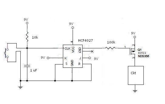
So I decided to use HCF4027 IC. But even though it is a J-K flip flop, I am unable to achieve toggle function. I connected J and K to Vcc, S and R to GND. I am applying a pulse using a normal switch and RC circuit to handle debouncing.
Please let me know if I am doing anything wrong.
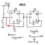
Further, is there any simpler method to implement this toggle function?[To reduce the Size of the circuit]
I am using a J-K flip flop IC 74HC73 for a toggle function to switch on and off a MOSFET. This IC works fine till 6V. But I need to switch a voltage of 9V.
So I decided to use HCF4027 IC. But even though it is a J-K flip flop, I am unable to achieve toggle function. I connected J and K to Vcc, S and R to GND. I am applying a pulse using a normal switch and RC circuit to handle debouncing.
Please let me know if I am doing anything wrong.
Further, is there any simpler method to implement this toggle function?[To reduce the Size of the circuit]