Continue to Site

Welcome to EDAboard.com

Welcome to our site! EDAboard.com is an international Electronics Discussion Forum focused on EDA software, circuits, schematics, books, theory, papers, asic, pld, 8051, DSP, Network, RF, Analog Design, PCB, Service Manuals... and a whole lot more! To participate you need to register. Registration is free. Click here to register now.

What does ""active low" mean ?

Status
Not open for further replies.

henninggs

Member level 2
Member level 2
Joined
Nov 10, 2011
Messages
45
Helped
2
Reputation
4
Reaction score
2
Trophy points
1,288
Location
Denmark
Visit site
Activity points
1,688
Hi.
I'm new to all this and learning every day.
This might be a very basic question and I do think I have understand it the correct way, just need to be sure.

I have a quad bus buffer, the 74HC125. In the data sheet it says:
The “125” is identical to the “126” but has active LOW enable input

This means that if there is no signal going to the !OE pin the device is enabled, right ?
But does "active low" also mean that the device is enabled EVEN if there is no current on the Vcc pin ?
Is the 74HC125 "enabled" when I hold it in my hand not connected to anything - or will the state be "undefined" if no power is supplied?
 

Active Low means Device/Pin will be active when Low Voltage (0v) is applied to it. You must apply +5v to vcc to make chip working.

I clear this concept with simple example. You know if inputs of both AND gate is 1 output is 1. But if both inputs are active low, then you will get output 1 only when you apply 0 to both inputs. (youcan think of it as NOT gate connected to each input of that AND gate).


Hope this helps
 
Active high means: logic low input (0) = "off", non-active. Logic high input (1) = "on", active.
Active low means: logic high input (1) = "off", non-active. Logic low input (0) = "on", active.

A logic IC like 74HCxx must always be powered (Vcc = 5V for example) before it does something sensible. How it responds to input signals, what "active", "enabled" etc means for a particular part: see datasheet.
 
Thanks you for your replies.

...A logic IC like 74HCxx must always be powered (Vcc = 5V for example) before it does something sensible...
Well, that was what I "feared" :)

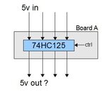
Let's say I have a bus and some nodes on that bus. The nodes are daisy chained. The bus goes into node A and then runs on to node B etc. At each node the bus runs through a "switch" (I was hoping that the switch could be a 74HC125) before it runs on to the next node. This means that each node can "break" the bus by disabling the switch leaving nodes down the bus unconnected.

I need to have a setup where a node only breaks the bus if it explicitly asked to do so. If the power supply to a node for some reason is suddenly terminated the hardware must ensure that the bus is not broken. Thus I need a circuit that when not powered rests in a "enable" state.

Se this image:
active_low.jpg
I need the 5v to run through board A EVEN if there is no power supply to the board.

How can I do this ?
 
  • Like
Reactions: munzir

    munzir

    Points: 2
    Helpful Answer Positive Rating
Can you tell us some more about what you are trying to do? What purpose each node serves, and what kind of inputs / outputs it has? And how everything is powered?

Usually on a bus most things are always connected to it, and individual devices enabled / disabled to 'talk to' that bus at specific times. When it's the goal to daisy chain devices on a bus, one would normally daisy chain control signal(s) from one device to the next, not somehow make / break all bus connections.
 

I wrote the attachement based on one written by a college - Norm McLeod many years ago.

It should help you to understand the concepts of Active Hig & Active Low.
 

Attachments

  • Logic Circuits.pdf
    173.3 KB · Views: 291
  • Like
Reactions: munzir

    munzir

    Points: 2
    Helpful Answer Positive Rating
Yes, here is some additional info on my idea.

1. I'll have a standard rs485 full duplex network: One master multiple slaves. This I'll call the "Main network".
2. An extra twisted pair is added to this setup and is only used to send data FROM a slave TO the master and only to initialize the slave. (a maximum of one slave will be connected to this extra line at any given time)
3. So I'll have 3 twisted pairs in use for data transfer. 2 for the standard rs485 and one for an exclusive "Slave-TO-Master" connection.
4. So this extra line ensures that the connected slave will have an exclusive connection to the master, thus such a slave can communicate with the master without having any unique ID and there will be no worries about collisions.

My idea is to use this "Slave-TO-Master" connection when a slave is turned on. If a slave has exclusive rights to talk to the master, it can be assigned an unique address with very little effort. When the slave has got its address it switches to the "Main network" and it will now be a "normal" rs485 node.

For this to work, I'll need to have the slaves to be daisy chained on the "Slave-TO-Master" connection (Not the "Main network" that's is a standard multidrop configuration). If daisy chained it will give the slave the power to break the "Slave-TO-Master" connection thus ensuring that the slave will be the only one connected.

Each slave needs a "switch" in order to break the connection, but I would like to have a switch that is enabled if the power supply to a given slave is disrupted.

---------- Post added at 23:03 ---------- Previous post was at 22:59 ----------

@ljcox
A very fine explanation. Thanks.
 
  • Like
Reactions: munzir

    munzir

    Points: 2
    Helpful Answer Positive Rating
Status
Not open for further replies.

Part and Inventory Search

Welcome to EDABoard.com

Sponsor

Back
Top