Continue to Site

Welcome to EDAboard.com

Welcome to our site! EDAboard.com is an international Electronics Discussion Forum focused on EDA software, circuits, schematics, books, theory, papers, asic, pld, 8051, DSP, Network, RF, Analog Design, PCB, Service Manuals... and a whole lot more! To participate you need to register. Registration is free. Click here to register now.

implement counter using 16V8 !!!

Status
Not open for further replies.

herwis

Newbie level 5
Newbie level 5
Joined
Oct 12, 2011
Messages
9
Helped
0
Reputation
0
Reaction score
0
Trophy points
1,281
Activity points
1,355
Hi everyone ,
I need to implement up-down counter with synchronous clear, enable and open-drain output by using 16V8 chip. any help is appreciated because im new in this field.
thanks
 

I would recommend starting with a (software) tool tailored for that device and go from there.
One of the manufacturers of such a 16V8 is Atmel. Go to their site and download the (free) WinCUPL software.
Other compilers for such a device are:
ABEL
LOG/iC
OrCAD-PLD
PLDesigner
Tango-PLD

The 16V8 has only 8 macro-cells (8 flip-flops) so don't expect too much from it. At best you can have a 8-bit counter I guess.
I have no idea if the software tools have any other means of input, besides boolean expressions. So, in worse case, you have to create the boolean expressions for your required design.
 
  • Like
Reactions: herwis

    herwis

    Points: 2
    Helpful Answer Positive Rating
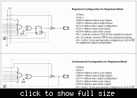
In 16V8 registered mode, open drain is only available for combinational macro cells. Thus you need an additional macro cell for each open drain output, reducing the maximum counter width to 4.

 
  • Like
Reactions: herwis

    herwis

    Points: 2
    Helpful Answer Positive Rating
thank u so much, but im kind of confused. could u give me more info about implementing the counter on 16v8 with clear and enable.
 

You didn't tell about your available design entry method. Assuming low level logic equations, you need to design a truth table for each counter FF, and check if it fits the eight AND terms available with 16V8. If you have a high level (e.g. VHDL or Verilog) design entry tool, you can use predefined counter macros or a behavioral description and the design compiler tries to fit it into the device.

I don't know your digital logic background. If your studying the topic, you'll find the login design methods described in your text books.
 
  • Like
Reactions: herwis

    herwis

    Points: 2
    Helpful Answer Positive Rating
Thanks guys,
I need just to draw the implementations on the avantis 16v8 diagram. i don't need the vhdl code.
the requirement is to implement the up/down counter, say 2 bit up/down counter with clear(i guess i can use PTD as a clear) and enable???
and it should be open drain output.
again I need the implementations without the code!
even if you help me with the equation will be appreciated.
 

We need an extra HOMEWORK prefix besides SOLVED. :p

Oh yeah FvM, while you're at it, could you please explain Fermi's formulation for the weak hadronic current density? kthxbye! ^^
 
  • Like
Reactions: FvM

    FvM

    Points: 2
    Helpful Answer Positive Rating
Mmm according to the creation of this thread and date. I assume you're taking some form of Electrical Engineering class and this is probably your last homework.

I'm currently working on a similar problem if not the exact same one.

Soo looking at the 16v8. (**broken link removed**)

I can only implement the counter using Outputs PIN 19..16(since these do feedback) in respect to Q3..Q0. (Since open drain output, i'm limited to 4 counters)

To get clear into a 16v8 I would use the PTD connected to all the AND gates feeding to ALL the macrocells. (right?) The output enable(low) input (/OE) will then have to be connected to PIN 2 since I need to use SG1=1 and SL0x=1. meaning I can't PIN 11(/OE).

Now my counter also has a choice of counting up or counting down depending on the Up-Down input which I believe would be connected to the SL1x of each XOR gate for inverted or non inverted outputs to toggle between up or down (right?)

My question is how exactly does open drain work on this device? I understand for open-drain I must have a pullup resistor to create a '1' logic but how would I go about that using other other macrocells limiting myself to only 4bits as stated above?
 

My question is how exactly does open drain work on this device? I understand for open-drain I must have a pullup resistor to create a '1' logic but how would I go about that using other other macrocells limiting myself to only 4bits as stated above?

You create a normal counter with 4 of the macrocells. The other 4 macrocells are used as the open drain outputs. They are set to output a constant '0', and the output enables are controlled from the counter outputs.
 

I made my life easy and implemented a 4-bit counter with OD outputs in VHDL and synthesized with Precision Synthesis under ispLEVER. As you can see from the report file, it fits a 16V8.

Code:
library ieee;
use ieee.std_logic_1164.all;
use ieee.std_logic_arith.all;

entity cnt4od is
port
(
  clk	:in  std_logic;
  clr	:in  std_logic;
  en	:in  std_logic;
  cnt_o :out std_logic_vector(3 downto 0)
);
end;

architecture rtl of cnt4od is
signal cnt_i :unsigned(3 downto 0);

begin
  process (clk,cnt_i)
  begin
    if rising_edge(clk) then
      if clr = '1' then
        cnt_i <= (others => '0');
      elsif en = '1' then
        cnt_i <= cnt_i + 1;
      end if; 
    end if;
    for i in 0 to 3 loop
      if cnt_i(i) = '1' then
        cnt_o(i) <= 'Z';
      else
        cnt_o(i) <= '0';
      end if;
    end loop;
  end process;
end rtl;
 

Attachments

  • cnt4od.zip
    1.8 KB · Views: 98

Status
Not open for further replies.

Part and Inventory Search

Welcome to EDABoard.com

Sponsor

Back
Top