Continue to Site

Welcome to EDAboard.com

Welcome to our site! EDAboard.com is an international Electronics Discussion Forum focused on EDA software, circuits, schematics, books, theory, papers, asic, pld, 8051, DSP, Network, RF, Analog Design, PCB, Service Manuals... and a whole lot more! To participate you need to register. Registration is free. Click here to register now.

Can't understand a symbol in circuit. PLeaseHELP.

Status
Not open for further replies.

yugal0007

Newbie level 6
Newbie level 6
Joined
Nov 14, 2011
Messages
14
Helped
0
Reputation
0
Reaction score
0
Trophy points
1,281
Location
Raipur, INDIA
Activity points
1,413
sch528.gif

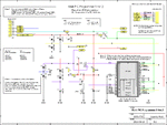
Schematic is attached (image file).
In schematic there's Vss. Now what i understand is Vss refers to ground.
also there's another symbol "#GND"
Now i can't diffrentiate this symbol with Vss.
Also there's a note written its attached here ed.jpg

Please clear my doubt. do i have to connect #GND and Vss with the GND terminal of my POWER SUPPLY UNIT???
or i have to do smthng else?
Please suggest.
 

Last edited:

Vcc and Vdd is for positive supply - Dont know why he gave vdd as signal gnd, probably he might get the signal switching from VDD and GND from that connector, but signal name VDD is wrong
Vee and Vss is for negative supply - #GND not GND.
 
Last edited:
Status
Not open for further replies.

Similar threads

Part and Inventory Search

Welcome to EDABoard.com

Sponsor

Back
Top