Continue to Site

Welcome to EDAboard.com

Welcome to our site! EDAboard.com is an international Electronics Discussion Forum focused on EDA software, circuits, schematics, books, theory, papers, asic, pld, 8051, DSP, Network, RF, Analog Design, PCB, Service Manuals... and a whole lot more! To participate you need to register. Registration is free. Click here to register now.

PWM IR2110 Half-Bridge duty cycle

Status
Not open for further replies.
It is current from power bus drawn by hbridge which determines power consumed. By monitoring this current, power output power can be controlled.
 

hello,

Actually I have a new problem now. It's very interesting for me. When I simulate my ccs c program on proteus. I get PWM signal what I wish. Here is an example for 25khz signal:

**broken link removed**

the frequency is nearly f=1/40us=25khz.

But on the other hand when I tested my hardware with scope, here is the figure:

**broken link removed**

My time/DIV = 10uS on the scope. So f=1/26us =38461 hz

on simulation, it works well, but in real life what is my mistake?

not: I tested it without connecting anything.

Thanks,
 
Last edited:

They are same in respect of duty cycle. Fequency difference may be due to different crystal frequency.
 

Hello,

I look for 80W 1:2 step up transformer. Actually, I dont use a transformer before and I dont know anything about it in practice.
I will use it on the output of my H-bridge circuit to amplify 300Vpp up to 600Vpp.


Here is schematic of my power circuit:

**broken link removed**

With kind regards,
 
Last edited:

Dear Alertlink,
Thanks a lot for making it understand,yours detailed explanation is worthwhile, you hve a rich knowledge no doubt.kindly make me understand about a point i m confused that is it possible for one to change the duty cycle i.e 50% to 25% from a IC like SG3524/PIC16f72 and then will it be possible to feed this 25% duty cycle to IR2110 further to feed H-Bridge.
 

Of coarse and this is the way how pwm works. In theory you can change pwm from 0% to 100%. Whatever pwm is set for, IR2110 will translate it to output drive to feed H-Bridge. SG3524,SG3525 are dedicated pwm ics.PIC16f72 has buitin pwm module which is controlled through software.
 

hello Alterlink.
I want your some valuable guidance on the following:-
1:-Is it possible for one to connect the transformer 50 Hz on the output of H-Bridge while feeding the high side mosfets with 12/24 volts.the transformer being used will be 24 v/220v turn ratio.I want to connect the 24 v side of transformer to H- bridge high side and 220 v for utility
2:-formula regarding to determine the duty cycle of IC PWM like SG3524.Regards
 

Last edited:

    meddy

    Points: 2
    Helpful Answer Positive Rating
Dear Alterlinks,
Lot of help,love to spending so much time, calculation of duty cycle is yet to be solved.regards
 

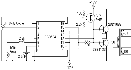
SG3524 has an error amplifier which corrects PWM duty cycle according to its input.. Play around with pin 1 and 2 of the device and this should vary your duty cycle, these are the inverting/non-inverting inputs of the error amplifier.
35_1321357310.gif


Study the datasheet and application notes for the SG3524. The pin 16 is the 5V reference.if we slide the pot so that the voltage from vref to the voltage at pin 2 This will simply adjust the duty cycle.
all you need is a voltage divider from the REF pin to the non-inv input pin2 and to ground.. use a pot, with wiper to the chip non inv... one side to ground, one side to Vref pin... Experiment with reistor values between pot and ground, and pot anf vref.. to get the response you want..

basically, 0-5v to the non-inv pin controls duty cycle... the rest is easy.. pin 1 to 9 directly( a resistor between pin1 and pin9 adjust the gain of amplifier).. pin 8 to ground, (forget soft start).. both pins 4 and 5 to ground until later when you worry about current limiting. ( Pins 4 and 5 are the inputs of another ampilifier to sense current, it also affects pwm)
The automatic error correction is a functional variable dircetly influnced by the feedback voltage obtained from sampling the output voltage....As the o/p voltage falls due to increased loading the, on time of the switching elements is increased, increasing the power transfer to the secondary side of the supply.
The switching frequency can be altered by changing the values of the resistor and capacitor on pins 6/7 respectively. Pins 4 and 5 will also impact on the duty cycle, these are used for curent sensing to detect overload, the switching action wil revert to a minimum duty cycle.
In fig6 of datasheet, there is a grapph to choos C and R to se the desired frequency. Page 4,5 cotains information about error amplifier.
 

Attachments

  • SG3524.pdf
    126 KB · Views: 237
Last edited:
dear interlink,
your good-self made each and every endeavour to make me and also others understand,no confusion exists now.I really enjoyed yours description which of-course is an excellent.
Regards.
 

dear alterlink,
Would you plz help to provide some circuits of charge controller analog type for inverter solar having capacity about 1500 watt bkz I am in dire need of that.regards
 

Hello,

I look for 80W 1:2 step up transformer. Actually, I dont use a transformer before and I dont know anything about it in practice.
I will use it on the output of my H-bridge circuit to amplify 300Vpp up to 600Vpp.


Here is schematic of my power circuit:

**broken link removed**

With kind regards,

Have alook at folowing link,
TRANSFORMERS
Use minimum frequency you are using, that is 25KHz. A transfomer, made for 25KHz can work on higher frequecy but not otherwise. As you are converting 150v to 600v, you need 1:4 turn ratio. If isolatin of output is not necessary, you can make a single winding autotransformer.
You can use 30swg, two wires,60 turns for primary and 240 turns of 32swg single wire for secondary. First wind half (120)turns of secondary,Then 60 turns of primary and then remaining 120 turns of secondary in a etd-33 core.


---------- Post added at 12:56 ---------- Previous post was at 12:49 ----------

[/COLOR]
dear alterlink,
Would you plz help to provide some circuits of charge controller analog type for inverter solar having capacity about 1500 watt bkz I am in dire need of that.regards
What is the voltage output and wattage of solar pannel and capacity of batteries. Inverter used is of 1500 Watts. Actually inverter has nothing to do with charging. Can you explain your whole setup?
 
Last edited:

Regards to respond,the solar panels 8 @90 w each comprising of total say 700w, the two batteries voltage 24v each having capacity of 200 AH.The required charge controller should deliver at least 20 to 40 amps. the solar panel's open voltage is 36v and on load is approximately 32 volts. Thanks for inconvenience.
 
Last edited:

If solar cells output is dirctly connected to battery it will charge it, the simplest way. For charging, it only require charging voltage to be greater than battery voltage, but for effiecient battery charging system there are many factors to be considered.,for example,
1. Power loss in DC power cable,
As this is low voltage and high current aplication, and if solar pannel is on roof top and batteries are on ground floor, there is extra loss in cables .It is better to connect pannels in series to get high voltage and low amperage to reduce power loss in cables.
2. Solar panels operate on certain voltage with maximim efficiency. Above and below that voltage, their efficiency reduces.
For example it is 32V and you want to charge 24V battery, You have to maintain load on soler pannel such that voltage drop due to load remains near 32V.
MPPT benefits
Maximum power point tracking controllers are basically microprocessor controlled switch mode converters that vary the duty cycle up and down, hunting for the panel voltage that relates to the maximum power output of the Photo Voltaic cells. These converter currently provide the highest conversion efficiency. They dynamically adjust to allow for changes in environmental conditions. An example would be if your battery is at 11V and the solar panel currently provides the optimum power at 15V, the MPPT would take in 15V at say 4A (60w) and provide the battery with 11V at 4,9A (53.9W) this includes a loss of 10% in the conversion. The same panel when connected directly may only put out 11V at 4,2A (46.2W).
3. In low sunlight conditions like early morning and near sunset and during cloudy sky when voltage developed are below 24V, system still can use power generated by boosting voltage to charge battery.
4. A grid tie inverter can directly share load with mains and reduce requirment on batteries. In other countries you can even sell back electicity.
5. There should be no load on batteries in dark by solar pannel.
6. Normal charge cycle of batteries according to recomended profile by manufacturer be maintained, like maximum voltage charge cycle, trickle charging etc.
Its upto you what features you want in your design. A commercial unit, look for features.
**broken link removed** practical designs are here. Power handling capacity may be icreased by changing some components,
**broken link removed**
Solar Charger 200ds230 rev2
SCC3 - 12 Volt 20 Amp Solar Charge Controller
SPC3 9 Amp in / 10 Amp out Solar Power Center

Have a look at solar chrging reference design.
 

Attachments

  • AN-2121.pdf
    936.8 KB · Views: 272
Last edited:

dear alterlinnk,
I hve' gone through yours detailed reply and found the SCC3,examined thoroughly ,the part TZ1 no.v7270/v727 which is TRANSZORB(transient voltage suppressor) is not found in website like alldatasheet.com datasheet.It may be due to its incomplete number.would you plz help how to find its specification.As I live in Lahore like you,can you guide that will it be possible to obtain from local markete.Regards
 

Have alook at folowing link,
TRANSFORMERS
Use minimum frequency you are using, that is 25KHz. A transfomer, made for 25KHz can work on higher frequecy but not otherwise. As you are converting 150v to 600v, you need 1:4 turn ratio. If isolatin of output is not necessary, you can make a single winding autotransformer.
You can use 30swg, two wires,60 turns for primary and 240 turns of 32swg single wire for secondary. First wind half (120)turns of secondary,Then 60 turns of primary and then remaining 120 turns of secondary in a etd-33 core.


---------- Post added at 12:56 ---------- Previous post was at 12:49 ----------

[/COLOR]
What is the voltage output and wattage of solar pannel and capacity of batteries. Inverter used is of 1500 Watts. Actually inverter has nothing to do with charging. Can you explain your whole setup?

Dear ALERTLINKS,

I consider about driving transducer. I want to drive 60W transducer. And for this operation, I want to use 70W-80W transformator. But how can I be sure that my transducer will not take upper 60W power. Some frequency such as resonance frequency, transducer may take maximum power,right? So maybe my transformer will also be damaged. Second question : is it possible that high voltages on the transducer side effects my H-bridge power circit? if it is possibble, how can I recover my power circuit?

Note:

"Use minimum frequency you are using, that is 25KHz. A transfomer, made for 25KHz can work on higher frequecy but not otherwise."
So I will design my transformer by considering 25 khz.

"As you are converting 150v to 600v, you need 1:4 turn ratio. If isolatin of output is not necessary, you can make a single winding autotransformer."

"You can use 30swg, two wires,60 turns for primary and 240 turns of 32swg single wire for secondary. First wind half (120)turns of secondary,Then 60 turns of primary and then remaining 120 turns of secondary in a etd-33 core."

I will try to design a transformer based etd-33 core as you said

Thanks

with kind regards,
 

60 Amp Modification for the SCC3-d1 12 Volt Solar Charge Controller
Link shows modification for upto 60A control. 75NF75 is eaily available FET.The 27V transzorb device prevents high voltage transient voltages on the input circuit from damaging. It is not a critical device. If you dont use it, its ok. A filter capacitor in input also reduces transient voltages which are rare. For 36V input a 27v device cant be used.
 

Status
Not open for further replies.

Similar threads

Part and Inventory Search

Welcome to EDABoard.com

Sponsor

Back
Top