Continue to Site

Welcome to EDAboard.com

Welcome to our site! EDAboard.com is an international Electronics Discussion Forum focused on EDA software, circuits, schematics, books, theory, papers, asic, pld, 8051, DSP, Network, RF, Analog Design, PCB, Service Manuals... and a whole lot more! To participate you need to register. Registration is free. Click here to register now.

[SOLVED] Parallel Transformers

Status
Not open for further replies.

roexile

Junior Member level 1
Joined
Nov 5, 2011
Messages
17
Helped
0
Reputation
0
Reaction score
0
Trophy points
1,281
Activity points
1,396
Have a nice day everyone,

If I'm going to connect primary and secondary windings of two 15A-Transformers in parallel, will I get 30A in all ?

Thank you:smile:
 

Yes you will get 30 amps but both the transformers should be of same specs. And also look for winding polarity, if any problem on output, interchange the connections of primary or secondary of any transformer.
 
If it is me and I need an output of 24V rated up to 15A and I don't have a transformer for it, I would use two transformers 12V/15A. Their primary windings will be connected in parallel and their secondary ones in series (in phase).
In other words, connecting the secondary’s in parallel is much like connecting two similar batteries in parallel. Theoretically, it works but practically any small difference in the voltage (or phase if AC) will add an internal current.
In case you have no choice but to use these two transformers, it is better to connect in parallel the two outputs of their diode rectifier. If their AC output voltages are exactly the same, we may say that we will get 30A for both. If there is a difference, this maximum will be obviously a bit less and it depends on how big their voltage difference is.

Kerim
 
Those transformers need to be of same specifications.Better both made by same manufacturer if you need them for serious application and optimum performance.
A small difference in their voltages or current will be effective in one way or other.
If their secondaries are rectified first and then connected in parallel,one of them will take greater load than the other unless its voltage reaches the same level.And if un-rectified secondaries are connected,there can arise the issues about one with a little high voltage sending that voltage back to the little weaker one and heating it up.Am i correct?
 
Yes it works fine for two similar transformer as long as you use a correct dimension of fuse for each secondary winding. Protects one transformer to be killed if secondary winding in the other transformer becomes shortcut or wrong phased. A minor back-current from one winding to the other is only possible for unloaded transformers but that current is too small to cause any problem.
Select size on primary fuses to do its job can be tricky on bigger transformers due to that start-current can be rater high, up to 10 times normal current. Slow blowing fuses is a must.
If you anyway intend to rectify secondary voltage, do that before connecting them in parallel as that further reduces risk that one transformer can kill the other transformer if somethings goes wrong.
 
E Kafeman.
good info you gave.Using transformers that way may be good for hobbyist and beginners. But for professionals and commercial products there are always certain regulations and safety margins,and doing so obviously violates them.And this forum is all about helping people to get there projects done with what is available to them easily.So, good talking.
 
UL, IEC, CSA... regulations?Is it a commercial household product should it fulfill safety standard IEC-60065 in Europe or UL-8730-1 in US. Safety problems related to EMI is regulated by FCC, EC, VCCI... but my input was NOT violating anything that any of these organisations regulates. Paralleling transformers are common in many commercial products. Two primary windings on one transformer or two transformers with one winding each is much the same situation. My advice was to use fuses that can act as fuses, which gives some safety margins to avoid big smoke but as far as I know is it fully ok to design something that can be self-destroyed anytime as long as it not causes public hazard.
 
Last edited:
how to connect two or more transformers in series ?

whats the advantage of it over paralleling a transformer ?

thanks
 

Dear Friends !
Hi
I think if you connect their secondary in parallel with together , it will be enough ( i tested it ) . but as RAza said , your transformers should be like together .
Best wishes
Goldsmith
 
how to connect two or more transformers in series ?

whats the advantage of it over paralleling a transformer ?
If the primary voltage of all the transformers is of same rating, you will connect all primaries in parallel and in Phase. Then you can connect the secondaries in series (all the windings must be of same current rating for safe working) as many as you need. There is no advantage of parallel or series over each other. If you connect secondaries in series it will add the voltage, like if you have three xformers of 5, 10 and 15 volts the result voltage will be 5+10+15=30 volts and the current will remain same as of ONE xformer. But if you connect in parallel thre xformers in parallel of 10 amps each (equal voltage of secondaries) the current will be added and yotal result current will be 10+10+10=30 amperes but voltage will remain same as of ONE transformer.
 
Thank you guys for these very useful information I have learned a lot from you.
 

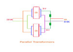
Is my pictorial diagram correct about parallel transformers?
parallel transformers.jpg
 

That will work ok. Maybe just not written in the drawing but it is better use of the transformers capacity to have full-wave rectifiers.
I can not see any fuse at primary side? It will be your fault when your whole neighborhood goes dark!
 
roexile,
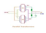
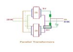
The connection on secondary side are to be adopted on primary side, too, if the transformers are of the same specs. Otherwise the primaries will be out of phase and you will not get any out put. As I have drawn in Dotted line and you need a capacitor also, otherwise output will be less because you will not get Peak reserved on output.
parallel.jpg
 
Raza

thanks for the correction...
 

roexile,
Sorry for the capacitor connections was wrong. Please correct it as in the image.
parallel.jpg
My apologies for an overlook.
 

Is my pictorial diagram correct about parallel transformers?
View attachment 63921

The main serious drawback in this configuration is that a DC current will flow in each secondary winding (due to the same half cycles). When the load current increases, the core (of each transformer) will start being saturated (in one direction) before reaching the transformer rated current.

Could you find how to avoid the DC current in each secondary winding?

Kerim
 

he main serious drawback in this configuration is that a DC current will flow in each secondary winding (due to the same half cycles).
I do not think as the each circuit completing before reaching the other. Both the windings in parallel and same same specs with being in Phase.
 

I do not think as the each circuit completing before reaching the other. Both the windings in parallel and same same specs with being in Phase.

Perhaps I read the diagram wrongly but I can't see how the current in each winding (secondary) can flow in both directions.
Isn't there a single diode in series with each winding?
I also see two separate cores.

Kerim
 

Status
Not open for further replies.

Part and Inventory Search

Welcome to EDABoard.com

Sponsor

Back
Top