Continue to Site

Welcome to EDAboard.com

Welcome to our site! EDAboard.com is an international Electronics Discussion Forum focused on EDA software, circuits, schematics, books, theory, papers, asic, pld, 8051, DSP, Network, RF, Analog Design, PCB, Service Manuals... and a whole lot more! To participate you need to register. Registration is free. Click here to register now.

[SOLVED] Urgent help is needed for SMPS project.

Status
Not open for further replies.

liteon

Full Member level 2
Full Member level 2
Joined
Oct 13, 2010
Messages
149
Helped
27
Reputation
54
Reaction score
27
Trophy points
1,308
Location
PAKISTAN
Activity points
2,510
Hi,
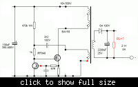
i need to figure out the working of following SMPS circuit.It is simple one mosfet based SMPS.


I want to make my first smps but first i need to ask few question to implement this project.

1- A little operational explanation.
2- Frequency depends on which part of the circuit.Can it be modified for different frequency.
3- How to determine the core types/size and number of turns for certain output say as in diagram 21v/5A.
4- How to determine the value of load resistor RL and inductor L at the output.
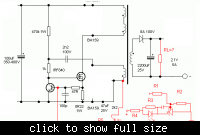
5- I want to regulate the out put voltage by using feed back loop circuit(colored red).How to configure the values of those resistors and capacitor.
 

sorry but you cannot drive a power mosfet like that in a switching regulator

it wont work
 
I asked a friend of mine about it (without the proposed component in red color) and he says it will be not efficient but it will work just fine.

Can tell me why you think so about it not being able to work.
 
No problem it will work, I think 47R resistor and 100p ceramic capacitor will determine the frequency. it is wired as flyback converter, if you name the components it will be easy to explain. search for flyback converters you will found similar circuits.
 

This is a self oscillating, transition mode, current mode control, flyback. Since it operates in transition mode, it's frequency is variable, and is defined by the line and load, and the transformer properties.

To make things simple, here's the thing with the feedback, and some other details eliminated, leaving a simple self oscillating converter circuit:

So on power up, the gate of the FET will be pulled up by the DC input voltage through the 470K resistor. The BJT is driven by the 0.22ohm source current sense resistor of the FET. Initially the current in the FET is zero, so the BJT is off. As the FET turns on, current will ramp up linearly in the primary, as the voltage across the current sense resistor will also ramp up. This will continue until there is about 0.7V across the current sense resistor (so Id=3.18A). At that point the BJT will be turned on and the FET gate voltage will be pulled down, and the FET will turn off. When this happens, flyback occurs in the transformer, and power will be delivered to the secondary. The key to the thing's operation is that the additional feedback primary winding will, at the same time, generate an EMF that, through 2.2nF cap and the 1K resistor, will reinforce the low gate voltage to the FET, preventing is from turning off even after the BJT is off. The EMF from that winding will persist until all of the energy has been transferred to the secondary. When that happens, the EMF will relax, and the gate of the FET will again be pulled up through the 470K and 1K resistors.

The FET is only allowed to switch on when the transformer has no energy in it, hence it is transition mode. Also, the peak current is defined by the Vbe of the BJT and the source current sense resistor, therefore it's current mode control.

Now add the feedback in:

The basic gist of the feedback is that when the voltage on the output gets too high, current will be sourced to the base of the BJT (during operation, that feedback primary winding also creates a DC bias voltage using the 47uF cap and the BA159 diode. That DC bias provides the bias for the phototransistor). This will induce a voltage across the 47ohm resistor, which will cause the BJT to turn before the drain current reaches the normal 3.18A). So in this way, the peak current of the converter is controlled in a negative feedback fashion.

The rest of the circuit is just for protection, filtering, etc.
 

Attachments

  • smps simple1.png
    smps simple1.png
    10.1 KB · Views: 619
  • smps simple2.png
    smps simple2.png
    14.3 KB · Views: 266
Thanks a lot people.
mtwieg, you made such an effort to explain it in such elaborated way, made easy to understand it.Thanks a million friend.I copied and saved the information you provided.

Now some one help me to find out the core size and number of turns to make the transformer.I have some cores salvaged from different SMPS.
I know the number of turns is related to the cross sectional area of center leg of the core.
The output power depends on size and type of the core.
Am i right?
How to figure out these?
 

Hi,
i need to figure out the working of following SMPS circuit.It is simple one mosfet based SMPS.


I want to make my first smps but first i need to ask few question to implement this project.

1- A little operational explanation.
2- Frequency depends on which part of the circuit.Can it be modified for different frequency.
3- How to determine the core types/size and number of turns for certain output say as in diagram 21v/5A.
4- How to determine the value of load resistor RL and inductor L at the output.
5- I want to regulate the out put voltage by using feed back loop circuit(colored red).How to configure the values of those resistors and capacitor.

You need EI-33 type core to achieve 21v-5amp.
Its better purchase an old pc power supply(150watt).
And use its original transformer,without any modification.
Irf 840 may not provide 105 watt.IRF460 is better choice.
Use varyable trimpot(1k) between adj pin of TL431 and negtive to control output volts.
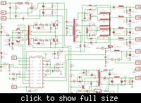
Schematic you attached,is a small flyback and almost use in atx pc supply for 5volt stand by (purple wire).
wish you good luck
 

Thanks a lot people.
Now some one help me to find out the core size and number of turns to make the transformer.I have some cores salvaged from different SMPS.
I know the number of turns is related to the cross sectional area of center leg of the core.
The output power depends on size and type of the core.
Am i right?
How to figure out these?
That's a much more complicated question than your first one... it all depends on what cooling method is used, what temperature rise is permissible, core material, power throughput, etc... I would start looking at nomograms from companies like EPCOS, they will generally give a lot of info helping with a decision. I recommend a relatively modern material, like 3C90 (as opposed to older stuff like N27).
 

You need EI-33 type core to achieve 21v-5amp.
Its better purchase an old pc power supply(150watt).
And use its original transformer,without any modification.

Well,where i live it is not possible to buy new cores of any type.Only salvaging from old equipment may help.
Luckily i always salvage those cores from old and broken appliances,mostly from tv and pc atx supply.
Now i have just one EI-33/29/13 core salvaged from an smps.
For this core so far i figured out following information.
AL value for this particular core is 2500(measured myself).
cross sectional area is 1.18cm2 or 118mm2.
Switching frequency is 15Khz upto 125Khz.
Max rated output is 75W upto 180W depending on operating frequency.
operating temp is -10C upto 100C.

Is it possible to determine windings now?If so how?

No problem it will work, I think 47R resistor and 100p ceramic capacitor will determine the frequency.
What is the frequecy with these values? what is calculation formula?


I am sure we can get till 28v from atx transformer in bridge or half wave rectification.And 14v in full wave with center tapped.
Every atx supply manufacturer have their own techniques regarding transformer.
Some transformer have 6pins or some have 7 or 8pins at secondary side.
But output volts like dc+5,+12, -5,-12v,+3.3v are same in every psu.
Can you tell how much pins are,of your transformer?
 

sorry but thats 21V and 5A.

Your circuit may work but it is bogus.
-If it was a viable and robust way to do a flyback then nobody would bother with PWM control chips.
-the mosfet in the scms above , is not being driven on quickly enough.
 

sorry but thats 21V and 5A.

Your circuit may work but it is bogus.
-If it was a viable and robust way to do a flyback then nobody would bother with PWM control chips.
-the mosfet in the scms above , is not being driven on quickly enough.
Sorry but,
Circuit like that are working well in pc power supplies.
 

Attachments

  • s_atx01aa.pdf
    63.8 KB · Views: 233

What is the frequecy with these values? what is calculation formula?
Those components to not really set the operating frequency. The 100p capacitor is just for noise immunity. The 47ohm resistor adjusts the gain of the feedback loop (amongst other things).

A full derivation of the operating frequency would be pretty messy, but suffice to say it depends on the input voltage, the transformer primary and secondary inductance, the load, the current sense components.... in any case it's not a fixed frequency converter, so it has a broad range of operating frequencies.

---------- Post added at 17:04 ---------- Previous post was at 16:58 ----------

sorry but thats 21V and 5A.

Your circuit may work but it is bogus.
-If it was a viable and robust way to do a flyback then nobody would bother with PWM control chips.
No, these self oscillators are pretty common in ultra low cost supplies where minimum efficiency standards don't apply. You're not going to be E-star certified with this topology.
-the mosfet in the scms above , is not being driven on quickly enough.
Not necessarily. Consider that the EMF from that auxiliary primary winding may be many tens of volts. The gate zener clamps it at 16-18V, but it will rise to that level quite quick because of that overdrive. Also consider that the converter is in transition mode. Therefore a slow turn on is fine, because it will be soft switching at turn on. At turn off it will be hard switching, but the BJT, along with the positive feedback in the auxiliary winding, will make sure it turns off pretty fast. So the gate drive works fine for this converter.
 
  • Like
Reactions: liteon

    liteon

    Points: 2
    Helpful Answer Positive Rating
I am sure we can get till 28v from atx transformer in bridge or half wave rectification.And 14v in full wave with center tapped.
Every atx supply manufacturer have their own techniques regarding transformer.
Some transformer have 6pins or some have 7 or 8pins at secondary side.
But output volts like dc+5,+12, -5,-12v,+3.3v are same in every psu.
Can you tell how much pins are,of your transformer?
.

First of all i forgot to mention that the core we are talking about was taken from atx supply based on tl494.It was used their along with EE-16 and EE-19 driver tranformers.
It has only one primary winding and no aux winding though it has 3 emty pins too on primary side.Secodary has 6-pins.
 

.

First of all i forgot to mention that the core we are talking about was taken from atx supply based on tl494.It was used their along with EE-16 and EE-19 driver tranformers.
It has only one primary winding and no aux winding though it has 3 emty pins too on primary side.Secodary has 6-pins.
EE-19 is for stand by 5 volt and vcc( 13.5v for TL494).
And EE-16 is a driver transformer,which drive two power transistor 13009,in half bridge configuration.

Circuit you are designing is same as EE-19.
But at primary side in EI-33 we have winding only for IRF840.
If we came to know aux winding volt than it will be easy.
Otherwise we have to open winding of EE-19 to get idea.
If aux volts are near 5 than we can use E1-33 in original condition.
 
  • Like
Reactions: liteon

    liteon

    Points: 2
    Helpful Answer Positive Rating
update.I found another identical circuit in a book although for reference only it was.Output 12V at 4A.
Not much explanation but transformer details are given.
Primary 30 turns ,wire 0.4mm.
Aux 3 turns ,wire 0.4mm.
Secondary 5 turns,wire 0.5mm *4.
Suggested core is not mentioned with type but only cross sectional area is given to be 1.2cm2, with 0.7mm air-gap. I have a core with same cross sectional area and air gap but it is large core E42 type.

So what you think now? One more thing ,there is output regulation implemented with 220R resistor and 11.2v zener diode at PC817 optocoupler.That means the output can be more than 12v with 5 turns.It may be 15v (3v for one turn).
 

Turns of transformer also depend upon flux density and operating switching frequency.
When you increase switching frequency turns become low.
The transformer you mention here,i think operated with mains 110volt.
Because primary turns 30 are not enough for 220v,in 1.2cm2 core section area.
Here problem we are facing only,aux volts=?
Once i rewind a transformer of 15v,3amp supply.
Size of transformer as i noted,EI-33 with core section area 1.3cm2.
Primary turns were 60,swg,30
Secondary turns=12,swg,23*3 for 15volt.
Secondary turns aux(vcc for uc3843)=10,swg,32.
Out put dc volts can be adjust with TL431 and pc817.
 

No the second design was also for 230v Ac.
Here we go. i just took risk to make the unit with the winding details and E-42 core as i told in my last post and put it to power 230v, nothing blown up but output went to 18v and i could draw 2A easily And nothing heated up.Had not yet implemented the regulation part.
But fast annoying ringing was coming from trafo,At 2A load it was reduced but yet not tolerable.Winding were in this sequence.
First primary. Middle AUX. Last Secondary.
I kept the transformer(did not dismantled it)
Wound another with same dimensions and changed the sequence of windings.
First half primary. Second secondary. third AUX.Final remaining half of primary.
Now the ringing was reduced too much i had to keep my ear close to the unit to here it, But the ouput increased with this core to 21v. I tested it for load of 2A again and nothing bad happened,ringing further reduced with load,heat sink for output diodes heated a little.Thats a normal thing.I could keep my finger on it all time and just felt warm.
Have not tried with EI-33 core yet.
 

Yes transformer which i rewind before have same technique half turns of primary at first and half are at last.
And secondary winding is in between.
Regarding noise of transformer,varnish is also a solution.
How many turns are for 21v and for aux?
Because transformer detail you mention in post #16 is for 12v.
Feed back circuit will keep the output volts stable with load or without load.
 

How many turns are for 21v and for aux?
Because transformer detail you mention in post #16 is for 12v.
I wound it for 12v as in my post#16.But with first transformer with bad ringing it gave 18v.And with second transformer it gave 21V.The cores were same size perhaps material was different.

Feed back circuit will keep the output volts stable with load or without load.
have not implemented yet.
 

Status
Not open for further replies.

Similar threads

Part and Inventory Search

Welcome to EDABoard.com

Sponsor

Back
Top