Continue to Site

Welcome to EDAboard.com

Welcome to our site! EDAboard.com is an international Electronics Discussion Forum focused on EDA software, circuits, schematics, books, theory, papers, asic, pld, 8051, DSP, Network, RF, Analog Design, PCB, Service Manuals... and a whole lot more! To participate you need to register. Registration is free. Click here to register now.

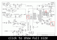
PIC16F72 Code and schematic for sine wave inverter.

Status
Not open for further replies.

Raza

Advanced Member level 3
Joined
Feb 10, 2002
Messages
828
Helped
266
Reputation
530
Reaction score
259
Trophy points
1,353
Location
PAK
Activity points
4,488
Hello Friends
I have been trying my utmost to get the CODE and Schematic for this project but no success. Got only incomplete diagram. Can any one help me for the same by posting here the complet information required or mail me at raza.ra@gmail.com, please.
Thanks to every one in advance.:|
 

I have this file, however, I haven't tested the entire thing.
 

Attachments

  • pic16f72_sine_wave_ups_with_source_code_and_schematic_1585.rar
    127.2 KB · Views: 3,471
Hi Tahmid,
Thanks a lot for the Diagram and the Software. Need some clarification if you or any one else can elaborate:
1. The switch on port RB2 (pin 23) meant for what? is this an Inverter ON/OFF Switch?
2. The jumper on port RA4 (pin 6) defines which Mode?
3. The LEDs on port RB3 to RB7 (pins 24 to 28) give what indications.
4. The Relay RL1 is added for what?

Raza

 
I haven't made this myself, so I can't really answer any of those questions. The relay most probably is for output switching.
 
Thanks Tahmid.

sahu......... you want a circuit for SQ WAVE inverter?
If yes I can upload it for you.
 
Thanks Tahmid.

sahu......... you want a circuit for SQ WAVE inverter?
If yes I can upload it for you.
sch + code(hex or source) for SQ WAVE inverter.it possible ?
 
AoA
If Any one interested in sinewave code+schematics+Transformer winding data and trouble shooting flow chart Plz contact me at 00000000 or xxxxxxx@gmail.com.
Regards

MOD: Every member is intrested in the said project. To advertise and contact you through email, its not a bussiness going on and too the post where you have posted it. If intending bussiness, we have a separate section for it. Too we dont entertain private sharing, Anything can be shared in open forum for the benefit of all members. read forum rules and announcements before posting.
 
WAS Naseer,
If possible upload it here so every one will be benefited from the post and if you are offering it commercially, send a Private message to the interested ones.
 
If Any one interested in sinewave code+schematics+Transformer winding data and trouble shooting flow chart Plz contact me at 00000000 or xxxxxxx@gmail.com. Regards
Every member is intrested in the said project. To advertise and contact you through email, its not a bussiness going on and too the post where you have posted it. If intending bussiness, we have a separate section for it. Too we do not entertain private sharing. Anything can be shared in open forum for the benefit of all members.
 

Hello Raza,
Pin 23 is for on/off the UPS
Pin 6 for energizing the PIC clock
Pin 24 to 28 for Main On LED,UPS On LED in case of Main failure,Charging Battery LED,Battery Full LED,Tripping LED when o/v or short cct occures,
I hope it'll be helpful.
ch wazir wazirptcl@yahoo.com
 
hello raza,
send complete diagram so that i guide u further
 

AOA
I do,nt know how to offer this thing but I paid for it.
 

sahu,
today 24_10_2011 so where Ur promise as u say
Sorry my dear, unfortunately I am an Heart patient and had open heart surgery for 5 arteries. Some time I am not able to exert much. I just completed the circuit diagram as the older one was in very bad shape. Now I will upload it in a few days. Sorry again for the delay.

ch wazir:
Thanks a lot for the offer, I am producing some designs of UPS already on commercial basis. I was trying to get feed back from Tehmid, and now I have clarified that all. Thanks again.
 

Raza sab visit this page,https://www.edaboard.com/threads/150224/
for hex and schematic of sine wave inverter cum ups.
pin 28(RB7),is low bat.
pin 27(RB6),chg.
pin 26 (RB5),over load
pin 25(RB4) indicate mains ok.
pin 24(RB3),inverter.
pin 23 on/off switch(push switch)
pin 21,22 empty.
 
Status
Not open for further replies.

Similar threads

Part and Inventory Search

Welcome to EDABoard.com

Sponsor

Back
Top