Pushhead
Full Member level 4

microstrip bend
Hello All,
Background story :
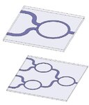
I'm designing a 2-way microstrip wilkinson power splitter in CST MWS. After a succesfull design of the basic splitter (S21~-3dB, S11<-20dB over most of the desired bandwidth) I have extended the output lines and added a 90 ° bend to both lines (design limitations).
The problem:
The 90 deg. bend have changed the S-parameters dramatically! i.e. S21,S11 have moved to a lower frequency.
Additional information:
The bend (line chamferring) was optimised for optimal S11 in a seperate model.
Boundary conditions are "Electric" with some added space above the lines.
Input port (50 Ohm) is at the bottom side of the PCB.
Output ports (50 Ohm) are at the Upper side of the PCB.
I know the splitter's response shouldn't change so drastically...
Can you help me with this ?
Tnx alot.
P.


