Continue to Site

Welcome to EDAboard.com

Welcome to our site! EDAboard.com is an international Electronics Discussion Forum focused on EDA software, circuits, schematics, books, theory, papers, asic, pld, 8051, DSP, Network, RF, Analog Design, PCB, Service Manuals... and a whole lot more! To participate you need to register. Registration is free. Click here to register now.

How do I connect a electret microphone to a PIC pin?

Status
Not open for further replies.

Windmiller

Member level 4
Member level 4
Joined
Mar 30, 2010
Messages
76
Helped
1
Reputation
2
Reaction score
1
Trophy points
1,288
Location
Sweden
Activity points
1,997
Hi!

My idea is to connect an electret microphone without preamp, with the output directly to a PIC pin.
I believe it should be possible without the preamp just because I'm only interested in getting the frequency, not the dB(volume)

My first question is..
Am I right? Will I get enough signal without preamp to count the frequency, or is it to low for the PIC to notice it?
I made my "googling", but ended up here asking my question instead.. hopefully someone knows by their own trial and error.

My secound question is.. this one's stupid I know..
The output signal from an electret microphone varies from 0V and up? It is never a negative value here? :roll:

Thanks!

Regards,
Morgan
 

Yes, I think you should be able to connect the electret directly to a pic pin, thru' a capacitor. Just remember that the signal would rarely be a ttl-level swing, so chose an input pin that can be configured as an opamp, and count every time the signal goes higher than your refernce. Alternately, configure an input as an ADC, and again decide on a threshold, to detect the signal. With this, you should be able to measure frequencies of a signal with an amplitude of a few 100s of mV. I would also use a clamping diode, just in case the mike gives a high pulse.

Regards,

Anand
 
I think, trying to attach mic directly to ADC input is a very bad idea.
First of all, you should find a CPU with the operational amplifier on-board.
Second, you need to apply at least low-pass filter.
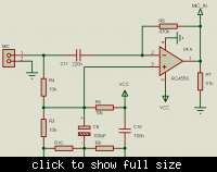
And the last one - it is a very hard mathematics you should use - Fourier conversion. I tried to do that on a low range PIC MCU. The results was not very clear. I will send you my schematic tomorrow from office. It stored on my computer. Anyway, I used external operational amplifier with a low-pass and hi-pass filter.
 
Hi

Maybe some of these schematics could be helpful :-D
 

Attachments

  • mic y speaker.PNG
    mic y speaker.PNG
    101.2 KB · Views: 143
  • electret mics.PNG
    electret mics.PNG
    27.2 KB · Views: 147
  • mic_amp_sparkfun.PNG
    mic_amp_sparkfun.PNG
    22 KB · Views: 182
You might want to consider using MSP430 series from TI. Some of them have integrated opamps or variable gain amplifiers. They are generally advertised as mixed signal controllers
 
Ard! Thank you for your answer, I'll try this, you made my believes even stronger now :)

---------- Post added at 21:56 ---------- Previous post was at 21:29 ----------

Eayrider83, thank you very much, i'm very interested in your schematics that would be very nice of you :)

Though, I don't need FFT in this one or DST because i'm going to use it in a place with no/little ambient sound where the microphone is going to pick up one single sin wave and test if it's around 220 Hz (A tone) by using timer and counting.. Still I'm very interested in your schematics. I'm starting to think that I need a preamp here.. maybe find a CPU with the operational amplifier on-board like you said.

---------- Post added at 22:03 ---------- Previous post was at 21:56 ----------

Akenafab, yes the 2-wire schema seems to be a good template to use, thanks!

---------- Post added at 22:16 ---------- Previous post was at 22:03 ----------

Poorchava, I'm going to take this chip into consideration, thanks for telling me about it.
 

Status
Not open for further replies.

Part and Inventory Search

Welcome to EDABoard.com

Sponsor

Back
Top