Continue to Site

Welcome to EDAboard.com

Welcome to our site! EDAboard.com is an international Electronics Discussion Forum focused on EDA software, circuits, schematics, books, theory, papers, asic, pld, 8051, DSP, Network, RF, Analog Design, PCB, Service Manuals... and a whole lot more! To participate you need to register. Registration is free. Click here to register now.

How to test this circuit with a DMM or with the help of any other circuitry ? thanks

Status
Not open for further replies.
How to test thyristor module............

View attachment 62423

thanks for your positive response .

In anode-cathode test (diode testing), you mention in each four cases that "no connect = ok" what does it mean by ?
DMM shows open or in forward biased condition it shows diode drop & in reverse biased condition shows open ?????

thanks , waiting for your reply
 
Measured with multimeter................

1-3 >> Open circuit
3-1 >> Open circuit
1-2 >> Open circuit
2-1 >> Open circuit

1-6 >> Low resistance
6-1 >> Low resistance
5-2 >> Low resistance
2-5 >> Low resistance

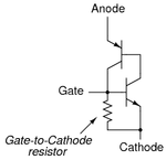
Equivalent schematic of SCR

SCR_InCon.png
 
Measured with multimeter................

1-3 >> Open circuit
3-1 >> Open circuit
1-2 >> Open circuit
2-1 >> Open circuit

1-6 >> Low resistance
6-1 >> Low resistance
5-2 >> Low resistance
2-5 >> Low resistance

Equivalent schematic of SCR

View attachment 62433

why 1-3 & 3-1 both would show open circuit ? one should show open circuit & the other one should show diode value drop when testing with diode testing range .........?

thanks a lot
 

Remember it is not diode its thyristor.
Thyristor is conductive only when anode=+ , cathode=- and gate has been triggered +
 
You can make your life easier by considering likely and unlikely failure mechanisms. Unless someone supplies you with faked components (no idea, if it could be problem in your country), you rarely will face a thyristor that doesn't trigger. Devices mostly fail short circuit, caused by fatal overcurrent or overvoltage.
 
Att: FvM
If you look posts #2 attachment & #4 , there is clearly said what are the readings measured with multimeter , when SCR is OK.
Still post #5 has question
why 1-3 & 3-1 both would show open circuit ? one should show open circuit & the other one should show diode value drop when testing with diode testing range .........?
My answer is to that question.
I agree , over 90% of fails i have seen in power semiconductors is clear short circuit . ( or blown away open circuit )
 
I find using a 12V lamp preferable to test SCR and TRIAC.
and trigger via a 1k (usually) resistor to gate.

(SCR) So in correct direction lamp will light and remain light when trigger removed.
The other direction the lamp should be completely off, triggered or not. If there is any glow
its failed either leak or a short.
 
if the trigger generator & pulse transformer working fine , then, would there be voltages between gate to anode, gate to cathode & anode to cathode ?
 

mosfets have a tendency to fail closed, while IGBTs have a tendency to fail OPEN in inverter topology. so i always used IGBT.
 

Status
Not open for further replies.

Similar threads

Part and Inventory Search

Welcome to EDABoard.com

Sponsor

Back
Top