Continue to Site

Welcome to EDAboard.com

Welcome to our site! EDAboard.com is an international Electronics Discussion Forum focused on EDA software, circuits, schematics, books, theory, papers, asic, pld, 8051, DSP, Network, RF, Analog Design, PCB, Service Manuals... and a whole lot more! To participate you need to register. Registration is free. Click here to register now.

MC34063A Step-Down Overheating

Status
Not open for further replies.
Yes the timebase is 5us/div. The inductors are 2x22uH/1A connected in series. The voltage across the current resistor (0R2) is 11.13V at one end and 11.10 to the other. So the difference voltage is 0.02V thus I=0.1A if you mean this.
 

I mean, that it would be interesting to watch the current waveform, not only the avarage value.
 

Hi friends,
In this circuit current limiting is the problem, I peak sense threshold voltage is 330mV. R4 (0.2ohm) is small for stepdown converter may be not able to produce a drop of 330mV resulting in higher switching pulse width and more switching current, in design sheets it is shown as 0.33ohm for step down. even we can further increase that value based on our load requirement. what is your load requirement?
regards,
murali_dece
 

My load requirements is about 600mA to 650mA. I have also tried with 0.4ohm(2x0R2 in series) but the result is the same. In the design of the Jenny IV-12 clock that i posted above he has used a pcb shunt instead of 0.2 Ohm resistor.
 

MC34063 efficiency isn't mind-blowing. In combination with inductor value and switching frequency, the losses in your design are more or less normal operation, I fear. One point is the rather high saturation voltage of the darlington output stage, switching losses is another. I would suggest to use a recent buck switching regulator, with 12 V input, synchronous operation is still in reach, but good standard switcher like National LM2672 would be fine as well.
 

MC34063 efficiency isn't mind-blowing. In combination with inductor value and switching frequency, the losses in your design are more or less normal operation, I fear. One point is the rather high saturation voltage of the darlington output stage, switching losses is another. I would suggest to use a recent buck switching regulator, with 12 V input, synchronous operation is still in reach, but good standard switcher like National LM2672 would be fine as well.
This is what I thought, but I went and did the calculations:

With Vout=2.4, Vin=12, RL=10, Vsw=1.2V (for the darlington), Rsense=0.4 and Vd=0.6, his output/inductor current should be 240mA, and his duty cycle should be about 28% (after accounting for the voltage drops of the switch, sense resistor, and catch diode). So the average switch/input current should be 67.2mA, but he says he's seeing almost twice that. So I can't explain the inefficiency and heating (especially when both drop over time) through normal converter operation, no matter how poor of a converter it is. So I think something must be busted; almost certainly that diode, if not the whole chip.
 

Well i had posted the same problem to avrfreaks forum and the guys from there mentioned me that at the datasheet example scheme there is an input 100uF capacitor that i didn't include in my design (i didn't thought that it is necessary as my voltage supply comes from a stable PSU). I gave it a try with this capacitor and the input current fell at 56mA as mtwieg wrote above and the chip stopped getting hot!
 
Hm, well that's a bit strange. I guess your 12V source must have been a high impedance enough for the voltage to sag a lot, maybe causing the darlington to desaturate even more? Oh well, in any case you will still want to replace that diode with a schottky.
 

I have tried it with two different power supplies one from PC and a homemade PSU. Both have the same result. I also have replaced the diode with the MBR1100.
 

Hi Tlogic,
I am having a DC-Dc converter based on MC34063 for driving white LED in Automobiles, It is also having an input filter of 10uF. may be this filter provides a path to induced switching noise on Dc bus to reach ground and provide stable DC reference to Ipk sense. Large value filters of power supplies may not pass the high frequency switching noise through them to ground. In your case lack of input filter may lead to failure of current control loop due to switching Noise.
 

Not having local supply decoupling (the 100uF) would mean the device sees more volts at switch off which would increase the heating in the chip - Regards, Orson Cart.
 
No, heat will be generated by current flow, In any configuration during switch off time open circuit voltage is allways eqal to supply voltage.
 

not if there is no local decoupling...

Hellow Orson Cart,
Please explain in detail about role of decoupling capacitors in switching circuits. I was little aware of Decoupling capacitors and how voltage will be raised in abscence of them.
 

if you don't have local decoupling - then the series inductance in the supply lines causes an overvoltage every time the switch turns off. Local decoupling absorbs this energy in the incoming lines. Regards Orson Cart.
 
In addition to the other coments I would add that this IC is intended to be PCB soldered with large dissipation surface. You are mounting it on a protoboard without appropiate heat dissiation and therefore is normal to get very hot...
See the datasheet https://www.onsemi.com/pub_link/Collateral/MC34063A-D.PDF Figure 16 (the IC has a big dissipation surface on the pcb).
When the IC temperature rises, its performance also is reduced (and efficiency) and it gets hotter. If you want to mantain output current and voltage while the efficiency decreases it is normal to have an increase on input current.

Ernest
 

Why are you putting a 22 ohm in series with coil?

The duty cycle in scope shot is way off. For 12v to 1.2v with passive diode should be less then 20%.

With 330 pF timing cap you are running close to high end limit for frequency. Freq becomes unstable near that point. Should be run below 70 kHz, 100 kHz is absolute max and it get flaky at that freq.

Make sure your coils can take the peak current without saturating.
 
Last edited:

if you don't have local decoupling - then the series inductance in the supply lines causes an overvoltage every time the switch turns off. Local decoupling absorbs this energy in the incoming lines. Regards Orson Cart.
Hello Orsan Cart,
Once again I gone through the circuit to understand in your view, but diode D4 connected to switch emitter (SE) provides low impedence path to regenerated energy during swith off time and it will be normall voltage at the momoent of switching on. Any way if over voltage is generated it is across the switch but not across power rail of IC or across feedback network, how converter will be influenced.
regards murali_dece.
 

Hi,
When i design MC34063, i will maintain 1.25V in the 5th pin and i will place a fast recovery diode like IN5819 in the 2nd pin. To avoid heat, i will choose my inductor and capacitor to maintain the frequency of 30Khz to 50Khz to operate at Normal input voltage. Place Rsc resistor in between 6th and 7th pin of MC. Refer the datasheet of MC.

Arrive the L and C value using the formula to work with the frequency of 50 Khz.
 

Tlogic,

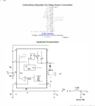
Use this calculator and design configuration :

**broken link removed**

1331211875189-uploadscreenshot-dot-com.png


You should not to have some problems on 100KHz.
 

Status
Not open for further replies.

Similar threads

Part and Inventory Search

Welcome to EDABoard.com

Sponsor

Back
Top