Continue to Site

Welcome to EDAboard.com

Welcome to our site! EDAboard.com is an international Electronics Discussion Forum focused on EDA software, circuits, schematics, books, theory, papers, asic, pld, 8051, DSP, Network, RF, Analog Design, PCB, Service Manuals... and a whole lot more! To participate you need to register. Registration is free. Click here to register now.

Cable termination on v.long cables

Status
Not open for further replies.

kc996

Newbie level 3
Newbie level 3
Joined
Sep 29, 2011
Messages
4
Helped
0
Reputation
0
Reaction score
0
Trophy points
1,281
Location
Aberdeen, Scotland
Activity points
1,328
Hi,
we use very basic low frequency 1200baud modems point to point over very long cable runs (up to 40km) To get this distance the cable is thick (5-10sqmm.) The modems are 100 Ohm impedance and the cable Z is also 100 Ohms. This length of cable commonly has a loop resistance(R) of around 120 Ohms.

My question is that although I am theoretically terminating a 100 Ohm impedance cable with the correct 100 Ohm impedance modems on either end does the fact that the cable has so much loop resistance not cause a problem?
For example does the local modem not see an effective load of the cable plus the remote modem giving 220 Ohms which would cause reflections?

Also if I want to put two modems at the remote site I can use a resistive star type splitter at the far end. This would normally use 3 x 33 Ohm resistors to split the signal two ways but keep each modem seeing 100 Ohms impedance, but again doesnt the resistance of the cable upset this?
Thanks very much, Kevin
 

If you have a 100 Ohm signal generator, a 100 Ohm symmetrical line and a 100 Ohm load, it sounds like a well matched system.
If all conditions stay as above, there will be no standing wave on the long line.

Now, 1200 bauds sounds close to 1 kHz which means that the wave length is 300 km. A half wavelength is 150 km, so your 40 km will be no problem if a mismatch caused a standing wave.

Connecting two modems ( loads/generators) directly in parallel will mismatch the line. I would advise to insert a 50-Ohm resistor in each of the four wires from the two modems to junctions with the cable wires.

Then everything depends on modem receiver sensitivity ; the cable is long and introduces a loss, and now you send and receive the signals to/from the line through resistive attenuators.

I will test your idea of parallel-connected modems in a laboratory, with the cable on a spool. This will show you if it works. Also, I do not know how your modems like running in parallel.
 
  • Like
Reactions: kc996

    kc996

    Points: 2
    Helpful Answer Positive Rating
Hi,
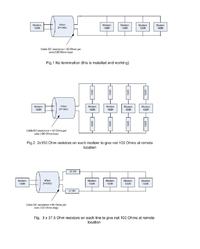
thanks for you reply! that makes good sense, the additional 4x50 Ohms along with the two remote modems combine to make the load at the far end of the cable equal to 100 Ohms.(see attached picture)
What I don't understand is that from the point of view of the remote modems, the impedance they now see is 166 Ohms, if my calcs are correct (204 Ohms if you include the resistance of the cable loop - which i dont know if you do or not???) Don't the remote modems need to see 100 Ohms also?
By the way the three modem system described does work without any extra resistors, I just want to understand the correct way of doing it ! Thanks again, K

http://obrazki.elektroda.pl/68_1317314017.jpg
 

You have a lossy cable which involves two consquences
- there is no exact impedance matching for your system
- reflections will be partly absorbed by the cable, in so far mismatch effects are reduced

Additionally, skin effect will cause frequency dependend attenuation and respective waveform distortions in time domain.

I don't understand the purpose of the paralleled modems. You have connected three modems in a star configuration which most likely causes connect problems unless they can be switched to half-duplex operation.
 
  • Like
Reactions: kc996

    kc996

    Points: 2
    Helpful Answer Positive Rating
Hi,
Thanks for that, the modems are used to control multiple industrial machines at a remote location, they only operate in half duplex master-slave mode so you can have as many modem as you want on a single line (within reason!)
I understand what you mean by a lossy cable, because there is no exact impedance matching possible what I want to know is the method you use to estimate the best resistor values.
From Jiripolivkas response above it looks as though you simply add resistors to ensure that the net resistance at the far end of the cable is 100 Ohms, is this the case?
I have attached an example with 4 remote modems, fig1 is the real working system as installed many years ago, fig 2 and 3 are my ideas on how to better terminate the system. What do you think of figs 2 &3 is either a good solution, is one better than the other.

Thanks again for you time!
 

Both impedance matched termination schemes are equivalent and should make no difference in matching quality. The individual resistor variant achieves some isolation between modems and can possibly achieve better signal-to.noise ratio, assuming that some interferences are emitted by the modem line interface.

If the modem operation is at the lower margin of input sensitivity, the unmatched, maximum level variant may perform better anyway.
 
  • Like
Reactions: kc996

    kc996

    Points: 2
    Helpful Answer Positive Rating
KC...from your drawing above (top block diagram of the 3), are you saying that you have a 100 ohm termination at EACH of the 3 modems? That is wrong. You want only the one farthest away to have 100 ohm terminaton...the two closer modems have no termination.

With such a long line, such a slow data rate, and so much resistive loss, you might even get away usikng NO 100 ohm terminating load at the end modem. There will be a reflection, but if the other two modems are nearby, that small ripple at such alow data rate might have no effect and data transfer. I would try it either way and see.
 
  • Like
Reactions: kc996

    kc996

    Points: 2
    Helpful Answer Positive Rating
Hi

how modems are connected to line, through resistive network on using transformer for line termination?
 

Hi all,
First of all let me say I never expected so much help so quickly!, thank-you. I think I have a much better understanding now. Just to answer a couple of points that were raised- Biff, I understand what you say about having ideally only 1 remote modem terminated with 100 Ohms, unfortuantely the modems don't have a termination resistor as such which can be removed, the 100 Ohms impedance comes from the combination of output driver IC which drives the line via an on board signal transformer to provide isolation.

At the risk of further complicating the story, we often run 40km out to a distribution box (just a simple junction box no active components or any termination of any kind) then from there we run stubs out to each of the remote modems each stub can be up to 2km in length ( I know this is bad practice but we have to do it this way for numerous other reasons!)

Thanks, K
 

Status
Not open for further replies.

Part and Inventory Search

Welcome to EDABoard.com

Sponsor

Back
Top