Continue to Site

Welcome to EDAboard.com

Welcome to our site! EDAboard.com is an international Electronics Discussion Forum focused on EDA software, circuits, schematics, books, theory, papers, asic, pld, 8051, DSP, Network, RF, Analog Design, PCB, Service Manuals... and a whole lot more! To participate you need to register. Registration is free. Click here to register now.

12v dc to 220v ac inverter,how can we convert it into ups?

Status
Not open for further replies.

pnjbtr

Full Member level 5
Full Member level 5
Joined
Feb 11, 2008
Messages
255
Helped
99
Reputation
198
Reaction score
89
Trophy points
1,318
Activity points
2,815
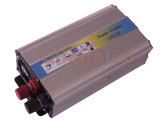
82_1316293854.jpg

Attached pitcure is a 12v dc to 220v ac inverter.
 

To upgrade for a uninterruptible power supply (UPS) need to add some rectifier (charger) - to convert AC power (from power grid) to DC power (to charge battery), supplementary controller - to control functions of rectifier (charger) to start or stop charging battery, how fast to change from grid power to battery power and for inverter when to start or stop power from battery to load, and some relays to change over time from grid power to battery power. In practice the off-line ups (the standard) switches to the batteries in 3 to 10 milliseconds, after the main power has been lost, but using the typical Inverter changes over in about 500 milliseconds. This gap is OK for household gadgets such as lights, fans, fridge, etc. but not OK for sensitive equipment.
 
To upgrade for a uninterruptible power supply (UPS) need to add some rectifier (charger) - to convert AC power (from power grid) to DC power (to charge battery), supplementary controller - to control functions of rectifier (charger) to start or stop charging battery, how fast to change from grid power to battery power and for inverter when to start or stop power from battery to load, and some relays to change over time from grid power to battery power. In practice the off-line ups (the standard) switches to the batteries in 3 to 10 milliseconds, after the main power has been lost, but using the typical Inverter changes over in about 500 milliseconds. This gap is OK for household gadgets such as lights, fans, fridge, etc. but not OK for sensitive equipment.
Thanks,
As i observe its an soft start inverter.
And no load current is only .4(400ma) from battery.
So if we keep it on every time there is no problem only 5watt load at mains power(grid power).
A seperate 12v charger and change over relays we needed.
Do you have idea about 10ms relay change over schematic.
Because 500m sec,enough time.
A computer can restart in mains failure with 500ms.
That is a nice aproach for rapid switching.
Computer power supply is cheap, provides 10A at 12V.It can be modified for charging purposes. Only output voltage have to increse and a seris regulator to control current. Or you can make one smps unit for charging yourself. Infact inverter is also simple, it can be made. Charger can remain permanently connected to battery as it shuts off when mains is interrupted.
Disconnect both wires of output with 12V relay. For normal use 220V relay can directly be used but for rapid changeover a small circuit can be used with 12V relay taking power from battery. It is also better to delay changeover few seconds when mains retun.It also stop chatter of relay.
A missing pulse detector can very rapidly detect mains failure. Set it to act when mains falls below 180 volts.

I have made such circuits in past using transistors for UPS for computers .
 
Last edited:

Hi,
There are a lot of Ready assembled kits available in the market plus you need a transformer of proper capacity according to the battery capacity. Simply pack this all in a separate box and thats it.
 

Hi,
There are a lot of Ready assembled kits available in the market plus you need a transformer of proper capacity according to the battery capacity. Simply pack this all in a separate box and thats it.
simply remember
WATT= VOLT× AMP
 
@Alertlinks, are you sure that computer power supply can provide 10 amp at 12v.
As i see only 5volts have much current almost 20amp.
If you have idea 12v/10 amp from computer supply please share.
Regarding smps charger,i remember once i modify an old supply of long range senao cordless phone(SN568) into a current limitter charger.
That supply was 15v 3amp smps,with uc3843,and pc817.
I can design again,but only problem chopper(high frequency transformer) not avail here.
As you mention we should deattach both wires of inverter,s out put.
I guess you are saying that negtive of 12v dc and 315v dc is common.
And it is hazardous if we use one wire of inverter with neuteral,as common.(we almost do in local ups).
@Raza sab,from where i can find ready assembled smps inverter kits?
If you observe,these kits are actually,(dc to dc converters 12vdc to near 300v dc without load).
In second stage we can convert 300v dc into 220v ac with h-bridge circuit.
But negtive of both 12v dc and 300vdc is common.
Due to common negtive we can face two problem.
1.we can not joint one wire of inverter,s output with neuteral.
If we joined neuteral it will damage transistor(IRF740),which we use in h-bridge.
2-Battery terminal become live,one can not touch.
regards,
 

Last edited:

Small computer supply for p3 or p4 is at least 350 watts. On most of them current output is written on a sticker. !2v at 10a is common. You have to modify circuit arround lm431 to increse voltage.
**broken link removed**
13.8 V / 15 A from a PC Power Supply
PC Power Supply
Converting PC power supply to power 12v charger? - RC Groups
very well.
I hope we can design a smps battery charger with pc power supply.
This charger will also cheap against smps 12v 10amp charger
Now important issue is isolation between negtive of 12v dc and 300v dc.
I hope it can be done with optocoupler(pc817 type).

best regards,
 
Last edited:

I have seen many inverters, battery and output is already isolated. Are you sure yours is not?
 
I have seen many inverters, battery and output is already isolated. Are you sure yours is not?
yes battery,s negtive and dc 300v ,s negtive is common.
It have TL494 at push pull 12v side.
two transformers,4 IRF1404 fets,(2 for each transformer).
And for h-bridge side IC NE556,4013 AND IRF740.
 

The common point can be seperated but there is need for 12v supply for out put circuit. This can be achieved by winding 3 turns of #28swg enemel wire on existing ferrite transformer. After rectification and filtering and using series regulator 7812.
There is always some space in ferrite transformer to push through some extra turns.
yes nica idea.
It suitable for isolation.
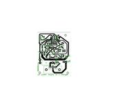
See attached circuit.
 

Attachments

  • 12v-220ac inverter.pdf
    120.2 KB · Views: 494
Last edited:

Small computer supply for p3 or p4 is at least 350 watts. On most of them current output is written on a sticker. !2v at 10a is common. You have to modify circuit arround lm431 to increse voltage.
**broken link removed**
13.8 V / 15 A from a PC Power Supply
PC Power Supply
Converting PC power supply to power 12v charger? - RC Groups
Yes you are right.
Pc power supply,s 12v can increase,after a tricky modification at pc817.
This pc817 is controlled by TPS5510P.
TPS5510,stops supply when it sense output volts +12 and +5 are increased to a max level.
When i read 13.8v at yellow and black wire.It swith off automatically.
After modification at 14v it can charge battery.
 

When we search for used computer power suppy, for example
**broken link removed**

It costs arround thirty to fifty dollars . I like to mention why computer power supply is advised to use. As our country is dump place for old computers, here we can get a working supply for 2 to 3 dollars and 2 repairabe for $1.
 
Last edited:

Although,we can increase volts of pc power supply and can charge a 12v battery with it.
But to control charging rate was a issue for me.
I observe at 13.8(float v) charging current was 14amp.(at that time battery was deeply discharged).
Second problem was,when we increase volts(14v) of pc power supply,we actually disturb over voltage and short circuit protection.
To control short circuit and reverse polarity.I select a circuit which can control output volt,charging current and short circuit protection.
This circuit can control two types of pc power supply.
One is forward type with Uc3842 & ss7n90 fet.
And second is half bridge type with 2 npn power transistor,TL494 & 339 ics.
Now an other important issue is,how can we charge 24v battery with pc power supply?
 

82_1316293854.jpg

Attached pitcure is a 12v dc to 220v ac inverter.
hello,
best way to convert the inverter into ups ,use the transformer in the output and a relay spdt be used for gid and inverter/ups.
 

A charge monitor circuit can control output voltage by replacing the trimmer for setting output voltage and hense current. You can check current control function manually by providing input to pc817 (0 to 6mA) through a variable resistor. Current monitor circuit using an operational amplifier can provide control signal for pc817 optocoupler.
 
Last edited:

UPS - You can see principe.


It is not difficult to see that the program is executed in a cycle of 100 ms synchronized by a timer.
In the body, the fastest, the loop is inserted reset WDT (team CLRWDT).

Divider connected to the WDT, set by a factor of division 1.
In such settings, in case of failure of the program, restart should occur
after 18 ms.

Ups.gif
 

Attachments

  • !!! UPS_PIC16F84.RAR
    133.1 KB · Views: 302
A charge monitor circuit can control output voltage by replacing the trimmer for setting output voltage and hense current. You can check current control function manually by providing input to pc817 (0 to 6mA) t hrough a variable resistor. Current monitor circuit using an operational amplifier can provide control signal for pc817 optocoupler.
Of course i already have control pc smps as a 12volt battery charger,with additional Lm358 and pc817 circuit.
But i urge to use pc power supply as a 24volt battery charger.
It is quite easy in forward type supply with uc3842 and 7n90 fet,because in this supply ic receive volts(vcc) from a fly back.
This fly back also provide stand by 5 volts.
Problem i am facing only in supply which have TL494 and LM339.
In this type supply we need bridge rectifier to increase volts till 28v.
Though supply have common cathode schottky diode.
 

Status
Not open for further replies.

Similar threads

Part and Inventory Search

Welcome to EDABoard.com

Sponsor

Back
Top